Hi all,
some more measurements attached. Lets analyze other day, it is too late now🙂
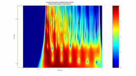
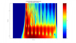
Tried trick from the thesis above, where two similar drivers are used to eliminate Pressure from equations if I understood. Put various rolls of tape between drivers since it wasn't possible to put them face to face ( too much magnetic opposition ) and no other tubes around than rolls of tape.
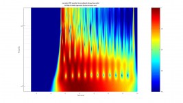
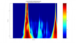
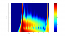
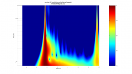
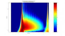
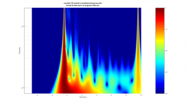
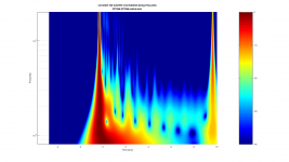
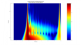
Anyway, put two drivers opposing each other through a tube. Excited the other and measured the other [ 1-3 ], measured from the exciting driver [ 4-6 ]. Both positions with three different heights of tape rolls in between. Then, one driver laying against table [ 7 ]. Number [ 8 ] is a "control", driver in the horn like in most of them previous posts, probed. Last two [ 9-10 ] are the horn facing a table top, number [ 10 ] has battery make -contact as signal.
Few first thoughts
1. alright, we see reflections in these spectograms!
2. when the diaphragm moves opposite direction on the transient, the top octave reflections looks totally different. This being with the opposing driver measurements [1-3] and the the battery make signal [10] (all previous posts use battery break signal).
3. Dang it's late, gotta go sleeping.
Have to do the opposing drivers measurements with amplifier and proper test signal for comparison. Also, try out "the control" [8] setup with battery make signal. Such fun!😀
What do you think?
some more measurements attached. Lets analyze other day, it is too late now🙂
Tried trick from the thesis above, where two similar drivers are used to eliminate Pressure from equations if I understood. Put various rolls of tape between drivers since it wasn't possible to put them face to face ( too much magnetic opposition ) and no other tubes around than rolls of tape.
Anyway, put two drivers opposing each other through a tube. Excited the other and measured the other [ 1-3 ], measured from the exciting driver [ 4-6 ]. Both positions with three different heights of tape rolls in between. Then, one driver laying against table [ 7 ]. Number [ 8 ] is a "control", driver in the horn like in most of them previous posts, probed. Last two [ 9-10 ] are the horn facing a table top, number [ 10 ] has battery make -contact as signal.
Few first thoughts
1. alright, we see reflections in these spectograms!
2. when the diaphragm moves opposite direction on the transient, the top octave reflections looks totally different. This being with the opposing driver measurements [1-3] and the the battery make signal [10] (all previous posts use battery break signal).
3. Dang it's late, gotta go sleeping.
Have to do the opposing drivers measurements with amplifier and proper test signal for comparison. Also, try out "the control" [8] setup with battery make signal. Such fun!😀
What do you think?
Attachments
-
 1-hf10ak-hf10ak-opposite-8-shortertube.wav-constant-Q-2d-norm.png180.1 KB · Views: 245
 -
 10-hf10ak-sth100-probe-7-table-btr-on.wav-constant-Q-2d-norm.png116.9 KB · Views: 108
 -
 9-hf10ak-sth100-probe-4-table.wav-constant-Q-2d-norm.png137.9 KB · Views: 98
 -
 8-hf10ak-sth100-probe.wav-constant-Q-2d-norm.png100.6 KB · Views: 103
 -
 7-hf10ak-hf10ak-same-8-table-128k.wav-constant-Q-2d-norm.png123.2 KB · Views: 107
 -
 6-hf10ak-hf10ak-same-12-longtube-128k.wav-constant-Q-2d-norm.png124.3 KB · Views: 100
 -
 5-hf10ak-hf10ak-same.wav-constant-Q-2d-norm.png127.4 KB · Views: 227
 -
 4-hf10ak-hf10ak-same-7-shorttube-128k.wav-constant-Q-2d-norm.png128.8 KB · Views: 221
 -
 3-hf10ak-hf10ak-opposite-5-lngertube.wav-constant-Q-2d-norm.png191.2 KB · Views: 232
 -
 2-hf10ak-hf10ak-opposite-1-128k.wav-constant-Q-2d-norm.png182.6 KB · Views: 235
Last edited:
Well, a few things have already been said, a few haven't.
- Measuring the sound within the horn got a great impact on the response and reflections, the mic capsule is always very big in comparison to the throat or driver exit.
- Measuring the response of drivers x on horn y only gives an answer to x combined with y.
- To get a more universal answer, you'd have to measure the driver exit angle and the throat entry angle aswell as any step, tiny gap or seam.
- Reflections can happen at other points of the horn too.
- A lot of reflections just show as an unlinearity, which can often be compensated. More important are the standing waves or resonances, some of which show as distortion.
- Yor horn does not work well on your driver. However, it might do well on another driver. (or vice versa)
- Edges or gaps can easily be compensated with non-shrinking modeling clay. I've modified several horn adapters and a few horn/driver combinations sucessfully. That can be very easy or very difficult, depending on the geometry of the horn and if you can modify both separately because the access from the front is sometimes tricky on deep horns. In general, it's easy, you simply have to even out the gap/angle/step. After the modeling clay hardens, you can sand it down or file it.
ICG, thanks for your post!
There is no microphone involved in the measurements, i've been using the driver itself as a"microphone" simultanously, no amplifier connected, signal from battery contact transient.
I had a thought that some of the linear reflections (Gunnes papers) from the horn might show up in the measurements (reflect back to the diaphragm).
Can you analyze some of these photos? the goal (topic) is to measure horn reflelections back to throat. Could you help analyze/identify these measurements if they are showing any lineat reflections from the horn, that could be counteracted with preconditioning filter? Thanks!
ps. there is a small discontinuity between horn and driver, I'll try to smooth it out and see if there is some difference. I'm doing and posting these measurements here since I don't have skills to analyze them myself other than through simple reasoning 🙂 I guess the goal here is just to measure and identify reflections from the measurements.
Last edited:
ICG, thanks for your post!
There is no microphone involved in the measurements, i've been using the driver itself as a"microphone" simultanously, no amplifier connected, signal from battery contact transient.
I had a thought that some of the linear reflections (Gunnes papers) from the horn might show up in the measurements (reflect back to the diaphragm).
Can you analyze some of these photos? the goal (topic) is to measure horn reflelections back to throat. Could you help analyze/identify these measurements if they are showing any lineat reflections from the horn, that could be counteracted with preconditioning filter? Thanks!
ps. there is a small discontinuity between horn and driver, I'll try to smooth it out and see if there is some difference. I'm doing and posting these measurements here since I don't have skills to analyze them myself other than through simple reasoning 🙂 I guess the goal here is just to measure and identify reflections from the measurements.
tmuikku, I'm finally beginning to see what you've been doing...excellent work/thinking !! Thank you for forging on as you have...
I'll try to apply some simple reasoning to your graphs, maybe try the same experiments..
Yeah please do try at home 🙂 if this measurement setup somehow turns out to be usefull, and we end up reasoning whats what (counteractable linear reflections), we might be able to find out a simple measurement setup / guide to apply to any driver + horn combination.
There is no microphone involved in the measurements, i've been using the driver itself as a"microphone" simultanously, no amplifier connected, signal from battery contact transient.
I had a thought that some of the linear reflections (Gunnes papers) from the horn might show up in the measurements (reflect back to the diaphragm).
Well, you can ofcourse use a driver as a microphone but the problem there is, it does not necessarily behave the same as being driven by the coil. It can behave a lot different on the reflected sound because the force is put on the membrane at a different point (or rather multiple points on most compression drivers).
If you keep the voltage on, it will move to the maximum excursion, outwards or inwards and that changes the compilance, the higher the excursion, the stiffer it gets. That changes the resonance frequency. And the membrane is not in the resting position anymore, so there will be a difference to the behaviour when playing music. The little offset will not change the frequency of the reflection much but it 'changes' the compression chamber size and, more important, how the air can flow in or out. That gets worse if you switch the polarity to measure it because it goes from the one extreme position to the exact opposite.
If you switch it on and measure it after turning the power off, it's first at the maximum excursion, then the membrane/diaphragm will return to the resting position. However, it will take some time to do that, it will swing on the resonance frequence. Most compression drivers in a horn got several resonances, it will 'settle' on the most dominant one. While it swings back and forth, you'll get a doppler effect which, ofcourse, got an influence on your measurement, it shifts the frequencies of the reflections. I am not sure how much influence it has, it is probably too low in magnitude but that depends on the driver but with very short reflections it might indeed be a problem since it will be on a much higher excursion than if you'd just get the signal from an amplifier, where you can exactly determine how strong the signal and therefore the excursion will be and it will cease movement probably a lot quicker. Remember, with a DC voltage, the excursion will always be higher than with a needle impulse of the same voltage because at the impulse it has to overcome the compilance, which is not the case with the battery.
Can you analyze some of these photos? the goal (topic) is to measure horn reflelections back to throat. Could you help analyze/identify these measurements if they are showing any lineat reflections from the horn, that could be counteracted with preconditioning filter?
Well, in general, the shorter the decay is, the better. The frequency of it is important too, ofcourse. Higher up decay delay is usually more problematic.
Like I already said, you can't tell resonances of the driver or horn itself apart from the reflections. Since that is a methodical problem, I don't see much of an advantage to measure it this way instead of with a microphone in front of the horn since the effect is the same. With a mic the result is much less difficult to analyze and got a lot different influences less. In the end, you can't tell with both methods ('diaphragm mic', measurement microphone) how/if reflections in the horn occur.
Yeah please do try at home 🙂 if this measurement setup somehow turns out to be usefull, and we end up reasoning whats what (counteractable linear reflections), we might be able to find out a simple measurement setup / guide to apply to any driver + horn combination.
Again, a big thanks for the inspiration to stay with this....🙂 Hope I can chime in now...
I've tried using a driver as a mic with a small twist.
I was wanting to pop a compression driver with a signal, then use the same driver as the measurement mic to catch return horn reflections.
I spent half the morning trying to figure out how to pop the driver without blowing up my soundcard.
Then it hit me, use a coax CD (4594)...use one section to produce the pop, and the other to record it. My kind of simple !
So I've been popping the coax sections with a 1 sample dirac pulse, and recording the other section's impulse using Smaart.
Alternating which section is the stimulus, both on and off a horn.
Initial results look really promising, but I need to study/verify a few things before posting, and wait till the house is empty to get background noise lowered.
It's amazing how much the CD picks up as a mic 😀
Go mark1000!😀
Valid points ICG, thank you! The resonances are much shorter and the system is closer to real world aplication with L-pad in the circuit. However the battery test signal might make this useless measurement method..
Anyway, lets see what mark1000 results look like!
Mark, do you have windows machine? Ive modified the Elias' Octave script to work on latest Octave version, default settings will render the images I've been posting recently.
Then it hit me, use a coax CD (4594)...use one section to produce the pop, and the other to record it. My kind of simple !
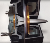
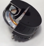
Uhm, that won't work quite like you are imagining. It's a coaxial driver but the membranes do not have the same distance to the exit. They got quite an offset to each other and the sound of the mid is dispersed towards the back, then going through a kind of tunnel and is reflected there several times and then leaded towards the mid and up, 180° from the initial direction. So you got already reflections within the driver and for both a lot different response. You aren't 'listening' with one membrane like with the other.
Neat idea, but praxis says otherwise.
Attachments
Uhm, that won't work quite like you are imagining. It's a coaxial driver but the membranes do not have the same distance to the exit. They got quite an offset to each other and the sound of the mid is dispersed towards the back, then going through a kind of tunnel and is reflected there several times and then leaded towards the mid and up, 180° from the initial direction. So you got already reflections within the driver and for both a lot different response. You aren't 'listening' with one membrane like with the other.
Neat idea, but praxis says otherwise.

ICG, Thx for those picts.
Yep, I've measured about a 0.05ms distance between the 2 sections' acoustic centers, with the mid section having the longer path. The impulses appear to show the reflections you speak of, along with inversion.
I'm far from understanding what I'm seeing, and I want to try more short FFTs in less noisy conditions before I post many traces.
But I can say the difference in the IRs is much more pronounced, horn vs no horn, than using the mid as dirac stimulus vs using HF as the stimulus.....at least once past 0.3-4ms as discussed next. So I have some hope re measuring horn reflects still...
From the little bit of experimenting, it seems like there are two different sets of impulse squiggles going on....I think the first set of squiggles within <0.3-4ms are the reflections you speak of. I had no theory for them until you bought them up. Thx again🙂
The second set, past that first grouping, and out to about 1.5ms may be horn reflections back into throat.
Obviously still guessing at this point....
Below is an IR using the HF as stimulus, and mid as mic.
You can see the cluster of rather evenly spaced full-volume oscillations under about 0.3ms. Do you think they are the reflections you speak of?
I'm thinking the taller peak at about 1ms, and the stuff around it, to be horn reflections..
What do you think?
(Spectrograph shows a 7kHz area spike in response right at about 1ms...)
Attachments

Go mark1000!😀
Valid points ICG, thank you! The resonances are much shorter and the system is closer to real world aplication with L-pad in the circuit. However the battery test signal might make this useless measurement method..
Anyway, lets see what mark1000 results look like!
Mark, do you have windows machine? Ive modified the Elias' Octave script to work on latest Octave version, default settings will render the images I've been posting recently.
Thank you tmuikku !
Yes I have a windows PC. But I have to admit I'm not all that good with programming..or even software for that matter. Heck, I'm having a hard time learning sketchup 😱
But if this project grows wings, I'd be happy to give Octave ye ole college try.
Thanks for the offer 🙂
No programming required: start Octave, select the script and click run. Then it asks you to select a wav file etc. pretty easy 🙂 I thought to use that Elias Octave script since it is used in the other horn measurement thread I've linked to. Of course please use anything that gives visual representation of the measurements and helps to get the reflections caught! If there was enough demand I might be able to whip up a web interface for the Elias script, but it is many hours of work, would be interesting exercise though.
Last edited:
Yep, I've measured about a 0.05ms distance between the 2 sections' acoustic centers, with the mid section having the longer path. The impulses appear to show the reflections you speak of, along with inversion.
The mid is also the 'weaker' part of the driver, it got much higher distortion (the difference increases more with the level) and the decay is also a lot less clean.
I'm far from understanding what I'm seeing, and I want to try more short FFTs in less noisy conditions before I post many traces.
But I can say the difference in the IRs is much more pronounced, horn vs no horn, than using the mid as dirac stimulus vs using HF as the stimulus.....at least once past 0.3-4ms as discussed next. So I have some hope re measuring horn reflects still...
Well, don't forget, without the horn, you have a lot less spl, the measurements have to be normalized. The response is a lot different too, to be really comparable, it has to be compensated for the response as well. It's very complicated, it's very easy to forget some aspects or to misinterpret the results.
The second set, past that first grouping, and out to about 1.5ms may be horn reflections back into throat.
Obviously still guessing at this point....
Yes, still guessing but your assumption seems reasonable. I would interpret that part the same, but, as I said, it's very easy to be mislead and not every seemingly logically conclusion translates into a fact. I think it's probably helping a lot to set the reflection (or impulse which seems to be a reflection) in comparison to the distance. 1ms delay equals to ~34,3cm sound travel distance. The travel distance starts at the diaphragm, not at the throat begin though. So, a reflection at 1ms occurred at half of that distance, 17,15cm, since the travel distance and therefore the time it takes for it towards that point and back again ofcourse add up. But it's also not impossible that it is the 2nd reflection of half of the distance, if the first reflection merged with the initial impulse and decay.
To identify it, it would probably help to use an adapter plate of a certain thickness between the horn and the driver since the offset would show in a delay equal to the added runtime/distance (twice the thickness) while the impulse decay will obviously not have an added delay. Ofcourse that's at the cost of possible additional reflections at the gaps from the driver to the adapter and the adapter to the horn and, ofcourse, also the possible different behaviour of the horn, since the throat was changed. I don't have any other ideas as a solution so maybe it's worth a try to help to analyze the situation since it gives the chance to identify or distinguish the different sources and parts of the measurements.
Below is an IR using the HF as stimulus, and mid as mic.
You can see the cluster of rather evenly spaced full-volume oscillations under about 0.3ms. Do you think they are the reflections you speak of?
I'm thinking the taller peak at about 1ms, and the stuff around it, to be horn reflections..
What do you think?
That would match the travelling distance of the suspected source, so it sounds pretty reasonable.
Last edited:
Found a paper that has some math and other details how to implement pre-conditioning filter: (PDF) DSP loudspeaker 3D complex correction
Found a paper that has some math and other details how to implement pre-conditioning filter: (PDF) DSP loudspeaker 3D complex correction
I'm a bit confused why you posted that paper. It is - simply put - about time/phase alignment of different drivers. It does not examine reflections within a horn (but briefly, the room). The DSP cannot change change the reflections within a horn/driver combination as it is inherited from its design/construction. Aside from that, the use of FIR-filters introduces pre- and postringing (aswell as noise), the former being much more critical and only exists in FIR but not in IIR filters, which means it's very important to weight up each dis-/advantages.
Hi ICG,
you are right, there is no thing about measuring horn reflections in the paper.
Please visit this paper if you havent: https://www.fulcrum-acoustic.com/as...dspeaker-transient-response-with-dsp-2005.pdf 🙂 Gunnes focusing, aka. temporal EQ. YouTube
I understood mark100 started this thread since he wanted to measure horn reflections back to throat to implement some of the things Dave Gunnes mentions in his paper (read the beginning of this thread).
In short, Gunnes has identified some parts of loudspeaker systems that are LTI two-port and thus can be fixed with pre-conditioned signal. One of those two-port systems is reflections from horn back to driver and as such those reflections are fixable with pre-conditioned signal (FIR filter), at least partially. Basically, counteract the reflection that reflects back to the diaphragm, from the horn, so it won't reflect out again for the listeners ear.
This thread is about measuring the reflections, but implementing a pre-conditioning filter is the final stage of mark100 venture for Gunnes focusing 😉
I've been trying to get grasp on the signal processing part of mr. Gunnes paper and it is hard to find info on "pre-conditioning" since I don't really know what to Google and have no experience in FIR filters or the math related. Don't know if the term "pre-conditioning" filter is a synonym of some other more widely used term or what. It is very hard to get into this from zero knowledge. Now that I found some info how to make such a filter I thought to post it here.
The paper I linked above citates the Gunnes paper(s), that is how I found it. I haven't read the paper thoroughly yet, but it seems they did a more general experiment to see if the overall horn system performance could be bettered with pre-conditioning filter by measuring response from a distance and taking some average out of those measurements and try to fix that. Instead of the minute detail stuff Gunnes does. They seem to use adaptive FIR filter, which was also mentioned in this thread earlier. I thought the paper helps to get a bit more info what it takes to to actually implement the Gunnes focusing. At least there are some new search words for Googling 🙂
Sorry, don't know FIR much at all, but the ringing has to be less of a problem than the "problems" that Gunnes have solved with it.
Cheerios!
Last edited:
Hi ICG,
you are right, there is no thing about measuring horn reflections in the paper.
Please visit this paper if you havent: https://www.fulcrum-acoustic.com/as...dspeaker-transient-response-with-dsp-2005.pdf 🙂 Gunnes focusing, aka. temporal EQ. YouTube
I understood mark100 started this thread since he wanted to measure horn reflections back to throat to implement some of the things Dave Gunnes mentions in his paper (read the beginning of this thread).
In short, Gunnes has identified some parts of loudspeaker systems that are LTI two-port and thus can be fixed with pre-conditioned signal. One of those two-port systems is reflections from horn back to driver and as such those reflections are fixable with pre-conditioned signal (FIR filter), at least partially. Basically, counteract the reflection that reflects back to the diaphragm, from the horn, so it won't reflect out again for the listeners ear.
Yes, thank you, I immediately understood what's the reason and counteractions were behind that, reduce the effect of the reflections by generating and adding a signal to the input and negating/cancelling the reflections. However, there are things you cannot change, namely the increased latency (okay, at Hifi usually not a problem, at live reproduction it actuall is), the inability to compensate for partial oscillation/breakup of the membrane since the reflected sound wave will likely affect also different areas and it it can't correct incoherent waveform reflections (aka uneven horn reflection over the diameter/surface) - the dispersion of the reflection will simply hit differently (in general more wide spread in surface) than the original dispersed sound wave. And, not to forget, the inherited pre-ringing of FIR filters (it doesn't work without FIR).
Sure, the 'error' or deviation of the signal might be lower than before and the resulting difference be small enough to be an overall advantage but, depending on the situation, that's not always the case. That's why the selection of the driver/horn is much more important.
Sorry, don't know FIR much at all, but the ringing has to be less of a problem than the "problems" that Gunnes have solved with it.
And that is exactly the point where I'm not with you. See, the reflections 'only' affect the decay and response (linearity), the initial impulse of the sound stays unaltered, which is very important to reproduce an acoustical event like the dynamic between two sounds or short impulses (ie. drums). With FIR however, that is no longer the case. And I think your lack of informations (mis-)leads you to a different, likely wrong conclusion. Don't misunderstand me there, FIR isn't 'bad'. It got great advantages but also big disadvantages and it has to be decided per case, a generalization is not possible.
So you want to know more about pre-ringing? Please, watch this video.
Yes I don't have fundamental understanding of FIR so this video by Gunnes has just about enough intellectual content in it YouTube 😀
The pre-ringing in the EQ example you posted was quite obvious, can't be happening here in such extent or they wouldn't sell any speakers at Fulcrum.
To me it seems that the preconditioning doesn't affect phase of the signal (but that must be wrong assumption? FIR filter means always phase shift in different frequencies causing the pre-ringing? ). The way I see it (without thinking FIR) that an algorithm adds delayed and altered signal back to the input signal, feeding the amplifier and thus the speaker, counteracting some of the resonances heard from a speaker.
Absolutely true, the better the driver + horn combination the better end result, with or without DSP. Gunnes works with PA speakers and particularly with coaxial speakers so they can't use the best of hifi type horns that measure best. But, it is very interesting concept and seemingly a good one altought I've never heard Fulcrum speakers. Their design principle is to handle problems in DSP that can be handled by DSP to have less compromises on the mechanical design (like the constant directivity horn they use, to get constant directivity, fix the response with DSP).
Latency of few milliseconds is important in monitoring live performance, but otherwise it is just taking a step (60cm) further from speakers.
The bolded part is what got me thinking the measurement procedure 😉 And now we are at a point where there is discussion about the topic (good, cool!) but no proper data yet or no proper analysis of the data. Some of the reflections are in Gunnes fixable list, can we measure them and then identify them?
Anyway gotta read and learn more to comment further 🙂
Thanks for your input ICG so far!
The pre-ringing in the EQ example you posted was quite obvious, can't be happening here in such extent or they wouldn't sell any speakers at Fulcrum.
To me it seems that the preconditioning doesn't affect phase of the signal (but that must be wrong assumption? FIR filter means always phase shift in different frequencies causing the pre-ringing? ). The way I see it (without thinking FIR) that an algorithm adds delayed and altered signal back to the input signal, feeding the amplifier and thus the speaker, counteracting some of the resonances heard from a speaker.
Absolutely true, the better the driver + horn combination the better end result, with or without DSP. Gunnes works with PA speakers and particularly with coaxial speakers so they can't use the best of hifi type horns that measure best. But, it is very interesting concept and seemingly a good one altought I've never heard Fulcrum speakers. Their design principle is to handle problems in DSP that can be handled by DSP to have less compromises on the mechanical design (like the constant directivity horn they use, to get constant directivity, fix the response with DSP).
Latency of few milliseconds is important in monitoring live performance, but otherwise it is just taking a step (60cm) further from speakers.
Gunnes is rather careful in his wording and states often that this stuff can be "partially" fixed and they might limit the preconditioning for some predefined signal voltage range for example, which is mentioned in the paper. And breakup as such is not in his fixables list for example.the inability to compensate for partial oscillation/breakup of the membrane since the reflected sound wave will likely affect also different areas and it it can't correct incoherent waveform reflections (aka uneven horn reflection over the diameter/surface)
The bolded part is what got me thinking the measurement procedure 😉 And now we are at a point where there is discussion about the topic (good, cool!) but no proper data yet or no proper analysis of the data. Some of the reflections are in Gunnes fixable list, can we measure them and then identify them?
Anyway gotta read and learn more to comment further 🙂
Thanks for your input ICG so far!
Last edited:
Hi guys,
Didn't mean to disappear.
Thank you for your continuing comments.
I've been working with the coax cd... one section as impulse, one section as mic.... idea.
Well, i should say I stopped working on measurements with it, and started working on a way to remove the initial impulses that are just the internal short path between the two sections.
So I've been trying to use a 1 sample impulse to trigger a microphone mute for about 0.2-4ms. Trying to be able to just measure return reflections.
I don't know how much FFT math has to try to make everything fit together, so I'm trying to eliminate what I know I don't want in the measurements.
Maybe it doesn't matter??? There's not much time to work with...I'm finding it takes a hell of a fast processor.
Anyway, yes tmuikki and ICG, you guys see exactly what I've been after.
ICG, my goal in measuring the reflections, as tmuikki mentions and Gunnes describes, is to use FIR to introduce time delayed inverses to the returning reflections.
I don't know if you've read his papers/patents, but he seems to have employed those ideas into a lot of different processing files for many different platforms, so that people can use whatever processing amplification they want with Fulcrum's speakers.
I've been looking a some of the FIR files for the q-sys platform, but I don't know enough about FIR to tell the difference in normal embedded EQ's and what might be some time delayed processing.
I do know enough about FIR to say I don't have any of the pre-ringing qualms folks talk about, unless filters are trying to handle too much Q for their size. I just don't hear it.
I've seen the Fab filter vid before...I'd like to give it more creedence, but he states in the first example he overplayed the EQ/crossover, and we have to admit, he IS selling something 😉
- Home
- Loudspeakers
- Multi-Way
- Measuring horn reflections back into the throat