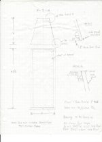
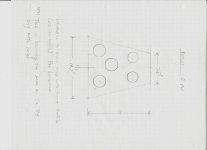
For the woofer, it is a Vented box with some wool and acoustastuff. internal vol 70L but I think I was off accounting for the volume of the vent. For the MID I posted the dimensions above in #19, Sealed with stuffing. I use Omnimic, Never used REWI would need a lot more information to determine that. Box dimensions, driver used, internal stuffing, is the box properly sealed and braced, on-axis frequency response and a waterfall chart. If you can measure with REW and send me the measurements I could look at it.
Attachments
Hi Jimbones,
is that the impedance of the "single" driver without crossover?
If yes, something is wrong, the second peak around 800Hz shouldn't be there
Im thinking there is a air leak. Looks like a vented curve.

What I mean is that I think that recessed mounting might be the cause.
To be honest, I rarely look at the impulse. Mine looks worse, but I'm relatively new to REW, so I may be of little help.
To be honest, I rarely look at the impulse. Mine looks worse, but I'm relatively new to REW, so I may be of little help.
Yes ! You have your first reflection ~3.4ms. You could gate the measurement til 3.1ms, quasi anechoic measurement above 300Hz. This measurement is good. You can try to have a larger windows 🙂6 ms gating
Your impedance curve is unusual. It looks like a Bass Reflex box. Do you have a leak in your mid box ? or Do we see the waveguide effect due to the mounting on the rear of the panel ? The mass of air front of the mid is resonating ? It becomes a mini acoustic line...
A minor resonance at 7kHz. You should test the second driver ?
Sound travels at approx 1ft / ms and 0.5ms implies 6 inches. You cabinet and baffle clearly have dimensions higher than this. This is mostly the cutout of the cabinet or the rim of the driver itself.

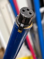
Get a proper mic mount. Like, mount a female XLR in a suited tube (same diameter as the mic body) of at least 3ft. Any normal mic clamp will cause strong reflections in the free sound field and thus interference in your measured signal.
Some claim they get away with using acoustic foam around the clamp (think of some fluffy cone around the mic) but the above solution is simply better.
Some claim they get away with using acoustic foam around the clamp (think of some fluffy cone around the mic) but the above solution is simply better.
Attachments
What about the top of the box overhanging the baffle. Maybe tape across there, and see if it changes.
OK so that was one of my questions. How important is it or is it inconsequential. The impedance curve is definitely wrong. Im thinking correcting that is higher in pecking order.What I mean is that I think that recessed mounting might be the cause.
To be honest, I rarely look at the impulse. Mine looks worse, but I'm relatively new to REW, so I may be of little help.
@temp25 yep tried that, no change. I added more stuffing to the midrange enclosure , no change. In thinking about how the recess affects the mid the low frequencies should not present a problem but the higher frequencies will be an issue. what are your thoughts. Is there a way to measure or calculate at what frequency that occurs?
OK so I ran a sim in WIN ISD in a 72 liter closed box the f3 is 35 f6 is 28hz. I could replace the vent with a plate....
I thought you were only measuring the mid-woofer. Is the mid-woofer in its own chamber? How big is that chamber? When you took the impedance curve is it only the mid-woofer that you measured? Did you have any crossover parts on it?For the woofer, it is a Vented box with some wool and acoustastuff. internal vol 70L but I think I was off accounting for the volume of the vent. For the MID I posted the dimensions above in #19, Sealed with stuffing. I use Omnimic, Never used REW
I would go sealed if it goes that deep, unless excursion, and SPL play a big roll. You might possibly make some nice looking port plugs, and have the option depending on the situation.
I would just measure the response, and decide from that. Unless... Unless it's not too late to mount from the front. Mounting from the front should help alignment to the tweeter as well.@temp25 yep tried that, no change. I added more stuffing to the midrange enclosure , no change. In thinking about how the recess affects the mid the low frequencies should not present a problem but the higher frequencies will be an issue. what are your thoughts. Is there a way to measure or calculate at what frequency that occurs?
YesIm thinking correcting that is higher in pecking order.
You should do a waterfall or a sonogram to visualize storage energy.Is there a way to measure or calculate at what frequency that occurs?
Only the mid woofer no crossover. post 19 has the dimensions. the curve is only the mid wooferI thought you were only measuring the mid-woofer. Is the mid-woofer in its own chamber? How big is that chamber? When you took the impedance curve is it only the mid-woofer that you measured? Did you have any crossover parts on it?
That impedance response looks wrong for a driver in a sealed box. What is the driver that you're using? that second bump up in the impedance looks like there are crossover parts on it. Something's going on.
Jim, in your pic, the first reflection is a just before 3.3ms6 ms gating
Each ms is about 1 foot.
- Home
- Loudspeakers
- Multi-Way
- Measurement Issues