One question that should be asked is just how good the CMRR really needs to be here. I'm probably missing something, but there shouldn't be large amounts of common-mode noise anyways, particularly since there probably won't be a lot of long cable runs feeding this.
What I need to think more about is how it affects things when this is looking at a single-ended source (like a power amplifier). Of course, that depends on how it's connected to said amplifier.
What I need to think more about is how it affects things when this is looking at a single-ended source (like a power amplifier). Of course, that depends on how it's connected to said amplifier.
I'm going to walk back my previous post a bit. Not the first time I may have been wrong. 😱
I now understand the 'B opamp is supposed to experience the same common-mode distortion as its 'A brother and subtract it from the 'A output. It's an interesting idea and I'm curious how well it might work.
I'm still concerned the paired opamps might oscillate. Each stage will exhibit mild gain peaking near its unity-gain cutoff frequency near 50MHz. There may be enough gain and phase shift to provoke oscillation. If so, a modest amount of lag-lead compensation between A's output and B's input should restore stability. (The compensator would consist of a series R between A's output and B's input, plus a R and C in series shunting B's input to ground.) At audio frequencies the network should offer negligble loss so that each opamp will experience the same common-mode voltage.
Good luck. Cheers!
This particular circuit is something I'm going to need to breadboard to make sure it doesn't have issues. It's just a preliminary design at this point.
The Boonton has fuses and I have blown them on occasion. Usually the one to ground when it should have been floating. . . Still no fuse is as fast to fry as the transistor at the input of an opamp. The light bulbs distortion contribution will be effectively nil unless you get a low enough frequency and high enough current for some modulation. There may be some good ideas in some DVM's. I looked for a schematic for the Keithley 2015 with no luck. There is a schematic for the 2000 which has some good ideas.
I primarily work with recording, mastering and broadcast gear where balanced I/O is the norm.
As to common mode rejection I doubt it would be practical to build the attenuator with anything but 1%, or at most 0.1%, resistors. CMRR would be limited by the attenuator balance between legs except in the "direct" K4B/K4C closed position where the input feeds the INA/diff amp directly. I can't think of a situation when using attenuation where CMRR would be critical for most people.
The direct mode is only where CMRR and 100K input impedance would really matter to someone like me for making noise measurements. I battle environmental EMI on the bench. An input with good CMRR always helps.
When the attenuator is out of circuit the limiting CMRR factor, at lower frequencies, would mostly be the diff amp resistor value relative match where it could be made excellent (at least at audio frequencies) by simple selection. Capacitance balance with low value feedback and input resistors in the diff amp makes it less critical and you might not need a trim to get decent HF performance.
1% resistor match will yield just over 30 dB CMRR. Selecting to 0.1% relative match, which is do-able if you have a bag of 100 resistors, or just buying 0.1% parts will provide about 60 dB CMRR. Using precision parts in that one stage would be worth the effort to me.
I just re-checked my LME49720 latch-up data and with ±15V supplies the sample I tried would start-up with a 100K bias resistor. (My focus at that time was 9V supplies.) You could use 100K/leg input bias resistors when switched to direct. The attenuator impedance could be lower when in circuit. I have found that coupling capacitors, if they're large enough, will satisfy the LME49720's start-up bias current. This may be why many people haven't seen it...
FWIW I measured the CMRR on inputs on my Focusrite 2i2 (Gen 3) and the CMRR of one channel was only 30 dB. The other was 65 dB. I also use TI PCM4222 Evaluation A/D board and its far worse around 26 dB. The 1246 line receivers I use typically run 75 dB CMRR or better midband.
I can get better than 0.1% resistor match without too much issue. Assuming a Gaussian distribution, it will not take many resistors from a bag of 1% resistors to get a 0.1% match. Same goes for matching resistors using a bag of 0.1% resistors.
Capacitance is probably the bigger issue in that regard, so the layout will take some care.
Just out of curiosity, does anyone know how the "big guys" (Audio Precision, Agilent, etc) are sensing levels for the autoranger?
What I was thinking of doing, at least for the first version, is to make the RMS to DC converter (or peak detector or whatever solution is used) be on a small daughterboard. Then it would be easy to try a few different circuits. It would also be easy to implement manual ranging using a single and inexpensive rotary switch with a resistor ladder.
FWIW I just checked the Boonton's CMRR. This has not be calibrated in 5+ years.
10 Hz- 108 dB
100 Hz- 86 dB
1 KHz- 84 dB
10 KHz- 70 dB
100 KHz- 51 dB
The resistors are all .1% and there are several CMRR adjustments. No exotic IC's I have upgraded to LME49710 and rescaled the feedback resistors down by 10X which did help. I'm using an AD797 for the differential amp since that worked the best.
If I can make some space in the shop I'll try the same test on the Shibasoku for a comparison.
FWIW I just checked the Boonton's CMRR. This has not be calibrated in 5+ years.
10 Hz- 108 dB
100 Hz- 86 dB
1 KHz- 84 dB
10 KHz- 70 dB
100 KHz- 51 dB
The resistors are all .1% and there are several CMRR adjustments. No exotic IC's I have upgraded to LME49710 and rescaled the feedback resistors down by 10X which did help. I'm using an AD797 for the differential amp since that worked the best.
If I can make some space in the shop I'll try the same test on the Shibasoku for a comparison.
That's really quite good, especially for being a significant amount of time since calibration. The only question in my mind is how important it really is for distortion measurements.
It's surprisingly easy to get 0.1% relative match from a bag of 1% parts.
The level detector doesn't need low-level precision since it's controlling an attenuator. I made simple averaging FW one here: A Simple Two Channel Eight Step Bar Graph Audio Level Meter For Outboard Gear Without Using An LM3914, LM3915 or LM3916 - Pro Audio Design Forum
The above-referenced topology has the advantage that the gain can be scaled by varying one R. It can be modified to peak fairly easily by adding two diodes.
Other than response time to overload I'm not sure how much benefit there is to peak but LM339/LM393 comparators make fast peak detectors. I'm not sure what RMS buys you in this application.
I have a circuit collection of level detectors you might peruse. Level Detectors, Absolute Value, Peak and RMS - Pro Audio Design Forum
As someone else mentioned you'll want the Rfb resistor values around the diff amp and INA to be pretty low for noise so capacitive balance with 2K values might not be so hard to maintain.
What is the post attenuator output and K5B/C for? Monitoring? Is there any reason you can't use the INA outputs?
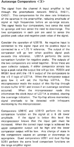
The Boonton uses an LM339 to sense peaks and a latch to scale up. Some simple logic could probably work OK with an up/down count for the level. The HP8903 schematic is pretty hard to follow so I'm not sure how that's done.
The AP system one uses the process attached (clipped from the sys 1 manual.).
The AP system one uses the process attached (clipped from the sys 1 manual.).
Attachments
What is the post attenuator output and K5B/C for? Monitoring? Is there any reason you can't use the INA outputs?
It's to switch between the INA and the differential buffer. The differential buffer is a way to drive an audio interface with balanced inputs without passing through the INA and then a differential line driver. This is for when you are using an audio interface with balanced inputs (which seems to be most of the good sound cards these days) and don't want to use any of the filtering cards.
Yeah, I was also starting to reconsider the inclusion of K5. Especially since I may change out the LM4562s for a FET input op-amp like the an OPA1642 or OPA1678.
Even at 100K, the bias resistors will have a loading effect on the attenuator. It may be advantageous to eliminate K5, increase the value of the bias resistors and change the op-amps to whatever seems suitable. Compared to the OPA1642, the OPA1678 has slightly lower voltage noise, about 3 times the current noise, marginally higher distortion (.0001% vs .00005%) and costs about 50% as much.
Even at 100K, the bias resistors will have a loading effect on the attenuator. It may be advantageous to eliminate K5, increase the value of the bias resistors and change the op-amps to whatever seems suitable. Compared to the OPA1642, the OPA1678 has slightly lower voltage noise, about 3 times the current noise, marginally higher distortion (.0001% vs .00005%) and costs about 50% as much.
It's to switch between the INA and the differential buffer. The differential buffer is a way to drive an audio interface with balanced inputs without passing through the INA and then a differential line driver. This is for when you are using an audio interface with balanced inputs (which seems to be most of the good sound cards these days) and don't want to use any of the filtering cards.
There's no harm in the auxiliary balanced output passing through the INA. Consider using the INA output to also provide the balanced converter feed by switching the INA to unity gain for that configuration. Would save op amps and keep both measurement paths consistent through the same set of op amps. You could re-purpose K5's 2 poles to switch the INA to followers by shunting the feedback resistors and switching Rg out. (You might see lower CM distortion by only switching out Rg.)
AP used NE5534's with 1M bias resistors. It can be done. There are tricks to manage Ib x Rbias and the common mode offset. You might consider a 5532/34 and use AP's tricks. One was providing bias current assistance by biasing the 1M bias resistors in the opposite direction of the nominal Ib x Rb offset. The second trick is that the following diff amp removes common mode DC.
It also occurred to me that you could use the single-ended diff amp output downstream as the sample point for auto-ranging. The input will momentarily overload whether auto-ranging operates feed-forward or feedback. By having the detector sample from the final single-ended output it doesn't load the input and can be tailored to keep the INA ahead of it in its lowest-distortion sweet spot. You also don't need a differential input for the detector.
Last edited:
The primary challenge with the peak detector circuits that have been discussed so far is that they won't work great at low frequencies without making the range switching unacceptably slow. I can think of three solutions.
1) Live with it. Relay chatter might be an issue at low frequencies, so testing below some frequency (maybe 60 or 100 Hz) will require manual ranging. A manual range override would therefore be provided.
2) Use a true-RMS detector IC. It will be inaccurate for non-sinusoidal signals, but maybe that doesn't matter since 95% of the use case for a device like this is sine wave testing. If there is a need to look at the spectral content of bizarre waveforms, one could always use the manual range override.
3) Throw a microcontroller and an ADC at the problem. This one is the least satisfying to me, but I would be willing to entertain the idea for the sake of an experiment, particularly if other solutions prove to be unsatisfactory. Atmega328s are about $2 and can be programmed using an Arduino for those of us who are "digitally challenged". They have a 10 bit ADC built into them. They also have a PWM output that could easily be filtered to drive the comparators. I know that one could eliminate the comparators entirely with the microcontroller, but this brings me to my final point with this.
Level sensing for the autoranger will be on its own little daughterboard. That way different solutions can be tried, especially since everyone's use case is a bit different.
One possible option for input protection is a pair of back-to-back 15V zeners on each input rather than the diodes connected to the power rails. They would need to be somewhat large, however.
Out of curiosity, does anyone know what the newer AP boxes are doing to limit the input current before it auto-ranges? I can't imagine they're still using an incandescent lamp.
I need to think a little bit about the best way to do the differential line output since I'm not entirely happy with the current differential buffer circuit. It needs to be really low distortion and really low noise. The whole common-mode distortion issue makes that a challenge. Does anyone know how much of an issue that is with some of the newer FET op-amps like the OPA1642?
The most recent R+S analyser still uses bulbs - you can see a teardown here: Rohde & Schwarz UPV Audio Analyzer - teardown and repair - Page 1
At 100Hz, our UPV-B1 has better THD+N than our SYS2722 (2722 is slightly better by 1KHz).
Methinks R+S is a firm that understands EMC.
At 100Hz, our UPV-B1 has better THD+N than our SYS2722 (2722 is slightly better by 1KHz).
Methinks R+S is a firm that understands EMC.
The most recent R+S analyser still uses bulbs - you can see a teardown here: Rohde & Schwarz UPV Audio Analyzer - teardown and repair - Page 1
At 100Hz, our UPV-B1 has better THD+N than our SYS2722 (2722 is slightly better by 1KHz).
Methinks R+S is a firm that understands EMC.
Interesting, and R+S certainly knows what they're doing in this regard. The main challenge is probably going to be finding a suitable lamp. From the searching that I've done, there don't seem to be a whole lot of 48V+ lamps around these days. Almost all of them use the bayonet base, which isn't my first choice purely from a size perspective.
The main challenge is probably going to be finding a suitable lamp.
Perhaps by quoting
Some digging reveals that AP used the 48ES lamp.
this one https://www.atlantalightbulbs.com/l...lbs/incandescent-miniature-0001-to-1000/48es/ ?
Long-term availability is a concern. Atlanta Light Bulbs is the only distributor that has them in stock. Again, I don't want to design around parts that might be really hard for people to get in 10 years.
To reduce common mode distortion you might consider bootstrapping the INA input op amp power supplies.
Take a look at this article by Dimitri Danyuk: https://www.proaudiodesignforum.com...anyuk_Electronic_Design_September_11_2008.pdf
Both INA halves require independent bootstrapping. Danyuk's circuit can be simplified to have the op amp drive external transistors to bootstrap itself.
Danyuk used a high source impedance example which would show high improvement but there should be some CM distortion reduction with lower source impedance.
There are some opamps that have been optimized for CM distortion. The OPA1656 I thin is one and a good candidate for this anyway.
I remember seeing a trick in some DVMs using depletion mode FETs as current limiters. The fet is switched off once some current flows and the on resistance is quite low. I could not find an example instantly. . .
I remember seeing a trick in some DVMs using depletion mode FETs as current limiters. The fet is switched off once some current flows and the on resistance is quite low. I could not find an example instantly. . .
- Home
- Design & Build
- Equipment & Tools
- Measurement Interface for Sound Card