Regrettably, the HolmImpilse manual is not to detailed..
But after messing around a bit, I figured out the "match" function under the "manipulation" tab.
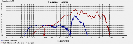
I chose 250 Hz for the centre matching frequency and a width of 100 Hz. This means that the program matches the signal level between 200 and 300 Hz.
You could of course do this manually by adjusting the dB offset of the two curves until they intersected at the desired point, but i found this function kind of neat. For this excersise, it is of course advantageous that the two curves to be matched has a relatively flat response in a range where they can be spliced.
This is why I wanted to get the far field measurement to extend reliably down to the expected "plateau" bleow the baffle-step roll-off.. or should i say roll-up? 🙂
Anyway, here's the result:
But after messing around a bit, I figured out the "match" function under the "manipulation" tab.
I chose 250 Hz for the centre matching frequency and a width of 100 Hz. This means that the program matches the signal level between 200 and 300 Hz.
You could of course do this manually by adjusting the dB offset of the two curves until they intersected at the desired point, but i found this function kind of neat. For this excersise, it is of course advantageous that the two curves to be matched has a relatively flat response in a range where they can be spliced.
This is why I wanted to get the far field measurement to extend reliably down to the expected "plateau" bleow the baffle-step roll-off.. or should i say roll-up? 🙂
Anyway, here's the result:
Attachments
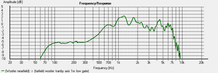
And now for the final wrap; turning these two curves in to one.
Again, HolmImpulse has a neat function called "stitch" under the manipulation tab.
This is very similar to the "match" function, you choose the centre frequency for where you want the splice,and the "width" of the splice. To me, it seems that within the width chosen, the two curves are averaged together to give a smooth transition.
I cose 250Hz and a width of 50 Hz.
But nothing happened!!??
Why, of course, the new spliced curve was obscured by the original curves! Hide those and the new spliced curve is there! come on, don't say I'm the first one to scratch the brain box over this one! 😀
Et Voila!
Attachments
So, what can I do with this alpine landscape then?
the curve looks rather rough, but then again, I set the resolution fairly high in order to have a close hard look at things..
Baffle step.. This tells me that the baffle step starts to roll up at about 300 Hz.
Looking at the aforementioned SEAS plot, this one suggests that roll-up starts at 200 Hz. As opposed to the 12L measurement box, my box contains some bracing, bitumen-sheet lining and additional lining with 12 mm "armaflex" foam to increase cabinet transmission loss. Despite the acoustic stuffing, this might rise the box Q a bit lifting the LF shelf a bit.. or it's just the measurement! *s*
Anyway, the discrepancy is hardly dramatic.
Now, where does the roll-up stop?
Again, the SEAS plot indicates around 1k.
Now, this is where things get a bit ambiguous.. My measurement rather suggests that the roll-up stops at around 700 Hz, followed by a bump at 1k.
The baffle step sim I did, predicts that the roll-up is continuous in to a 2 dB peak at around 1k.
First question: why is there no pronounced 1k peak in the SEAS plot??
I went back to the baffle sim and move the woofer closer to the bottom edge corresponding to the SEAS baffle. Well, the peak dropped, only by a dB or so, but it also became less sharp. I guess this observation combined with some measurement inaccuracy could at least partially provide some explanation.
It also tells me that I would have been better off placing the woofer closer to the edge, but I don't really feel like scrapping those boxes right now! 😀
Back to the issue of baffle step correction;
Should I consider a slope between 300 and 700 Hz, or up to 1k??
Now this is where I invite learned men to look at the curves and speak their opinion! 🙂
Good question, this is after all a LF measurement approach available to the DIY'er!
Well, according to how Vance Dickason describes this technique in the loudspeaker cook-book. you need to do this outdoors on a rather large surface with no immediate reflective surfaces, e.g. a parking lot.
This is in other words a very bad idea in Norway during winter time.
In my case, the near field approach seemed to work rather well, so I'll leave it with that for now! 🙂
The Dayton EMM-6 Behringer ECM8000 equivalent for $46 comes with a printed cal curve, and the file is available for download from the Parts Express site with input of the serial number....
Well, that Behringer should be a good choice then, perhaps even cheaper than building that WM-61a mic! 🙂
Since there were no further comments on the woofer response curve I arrived at by splicing near-and far-field measurement, I guess the next thing to do is to look at off-axis response and start contemplating crossover frequency and filter slope..
Since there were no further comments on the woofer response curve I arrived at by splicing near-and far-field measurement, I guess the next thing to do is to look at off-axis response and start contemplating crossover frequency and filter slope..
Member
Joined 2009
Elbert,
Thank you for taking the time to write this up. This discussion is extremely informative especially to a novice like myself.
I've seen people take measurements of the port in bass reflex systems. Is your system ported? Can somebody note whether there's anything more involved in measuring the port response than the typical process for woofers?
You asked about where to cross over your woofer, but you didn't show enough data to make any recommendations. At a minimum you'd also need the response of the driver that will play above it (I'm assuming it's a tweeter). Even better, you'd also have off axis responses for both woofer and tweeter and distortion for the tweeter. Then you could see where the polar responses of the drivers matched. You could also make sure that frequency was above the frequency where the tweeter started to produce significant distortion at the maximum level you're interested in (say 10% distortion for a reasonable limit) and below the frequency where the woofer starts to have objectionable response.
Boris,
Figured I wasn't the only newbie around, so it's good to hear that others have use and interrest in following this thread as well! 🙂
As the thread title says, I'm working on a closed box here. From what I've read, for a vented design you would just do an additional near field measurement of the port and splice that in or add it to the woofer near field. There are probably some tricks associated with that as well. Not sure this thread is the place to pursue that further, but it would perhaps be a good idea for someone to do a "suplementary" thread to this one??
Thanks John,
Some very clear advice on direction there!
I'll see if I can cough up some measurements suitable for this! 🙂
Simply matching up on-axis response of woofer and tweeter is probably doable even for a novice like me, but figuring out the best compromise based on a total polar response and distortion, well, that's probably where I'd be better of with some support! 🙂
Forget the Radio Shack SPL meters for measurements:
(From Comparison of ten room testing microphones)
Best, Markus
I would not trust those curves to prove much of anything; I was there when Ethan did those measurements and he did it 90 deg off axis even though I pointed out that it would not be accurate. The Neutrik mic was mine in those tests. The tests were done in room and Ethan's point was that most electret mics are reasonably flat below 1 kHz. It was intended to be a relative measurement, the wide response is due to room effects. Note that the Neutrik and the Earthworks are both 1/4" tip mikes of similar geometry, so they measure similarly off axis. Most of the others are 1/2" mics, or have about a 1/2" tip.
Last edited:
I would not trust any of those Radio Shack mikes, aimed correctly or not. That's what the curves show. By the way, the dark green curve is "aimed".
Best, Markus
Best, Markus
I would not trust any of those Radio Shack mikes, aimed correctly or not. That's what the curves show. By the way, the dark green curve is "aimed".
Best, Markus
They are probably not much worse than a home made Panasonic. You should not trust any mic that is not well built, calibrated, and with known stability. It depends, of course, on what your goals are for measurement. The analog RS mic was mine also, and I generally agree with you, it is why I also have the Neutrik and a recently calibrated ECM8000. The RS meter is handy for casual measurements, I'd probably replace the tip with a calibrated 1/4" Panasonic if it was my only mic.
What Ethan should have done, was use one mic with a calibration curve or get one of his mics calibrated and set up his measurement system with the cal file. Then show difference curves from the cal'd system for the other mics. Again, it was in room, and the source was a speaker, it was a worthless measurement IMO.
Last edited:
Remember that the "baffle step" is included if you are measuring in the far field, hence anything above 500-600 Hz does not require any modification. Its only the near field LF stuff that requires this and that won't have a significant effect on the crossover, only the "Q" of the LF HP. Read the ARTA paper, they do a good job of explaining this.
ARTA paper - do you mean the manual, or one of the papers at the site? Do you prefer Holm over ARTA, and for any particular reason if so?
Last edited:
I'd say the RS meter is significantly worse based on my somewhat limited experience - my panasonic home made mic was within +0,-1dB of my B&K calibrated measurement mic from 30hz to 8kHz. It was about -2dB at 14kHz and rolled off from there. Compare that to the ~+10dB of the RS meter above at ~6kHz. I'd say that's much less useful. If you designed a speaker using my Panasonic mic without correction, you wouldn't be that bad off. Using the RS would give you a really nasty response.
I'd say the RS meter is significantly worse based on my somewhat limited experience - my panasonic home made mic was within +0,-1dB of my B&K calibrated measurement mic from 30hz to 8kHz. It was about -2dB at 14kHz and rolled off from there. Compare that to the ~+10dB of the RS meter above at ~6kHz. I'd say that's much less useful. If you designed a speaker using my Panasonic mic without correction, you wouldn't be that bad off. Using the RS would give you a really nasty response.
I did say that I would replace the electret with a calibrated unit for any serious work if it was my only mic. Know your tools. My point was that Ethan's measurements were not very meaningful. It is widely known and discussed that there are issues with the RS mic above 2K, some think a generic cal file is good enough; I would disagree.
I'd definitely agree generic cal files aren't very helpful. Even with the Panasonics, I've seen a lot of calibration files (or at least curves available) that were not anywhere close to what my mic was.
I see people claiming that the Panasonics and the Behringer are within +/- 1dB over most of the range fairly often. My ECM8000 is +/- .75 dB from 40 to 12.5 K, whereas this one, calibrated at the same lab, is +4.37 dB at 10K. Not very consistent unit to unit:
http://www.diyaudio.com/forums/multi-way/144306-diy-measurement-mic-2.html#post1830665
I probably should let this thread get back to speaker design.
http://www.diyaudio.com/forums/multi-way/144306-diy-measurement-mic-2.html#post1830665
I probably should let this thread get back to speaker design.
ARTA paper - do you mean the manual, or one of the papers at the site? Do you prefer Holm over ARTA, and for any particular reason if so?
Ah, is this is AP4? http://www.fesb.hr/~mateljan/arta/AppNotes/AP4_FreeField-Rev03eng.pdf
- Status
- Not open for further replies.
- Home
- Loudspeakers
- Multi-Way
- Measurement approach, 2-way closed box