Thanks Ucla!
From what you explain, it is evident that with my current set-up it will only be so-so..
Not only am I cursed with a smallish living-room, but I also happen to live dead next to the busiest highway in the region. To top it off, there's also 50 cm of snow outside and temperatures as low as -20C this winter. Concluding that outdoors measurements is not really a viable option is perhaps a gentle understatement...😀
Well, for the low end, some clues to baffle step is what I had been hoping for.
Now I have to ask my self: Can I add some other facts to the equation in order to interpret the mediocre measurement data in any meaningfull way?
Whilst I ponder this, I'll be a good boy and run off to get the impulse measurement you requested! .)
Thanks Ucla!
From what you explain, it is evident that with my current set-up it will only be so-so..
Not only am I cursed with a smallish living-room, but I also happen to live dead next to the busiest highway in the region. To top it off, there's also 50 cm of snow outside and temperatures as low as -20C this winter. Concluding that outdoors measurements is not really a viable option is perhaps a gentle understatement...😀
Well, for the low end, some clues to baffle step is what I had been hoping for.
Now I have to ask my self: Can I add some other facts to the equation in order to interpret the mediocre measurement data in any meaningfull way?
Whilst I ponder this, I'll be a good boy and run off to get the impulse measurement you requested! .)
Remember that the "baffle step" is included if you are measuring in the far field, hence anything above 500-600 Hz does not require any modification. Its only the near field LF stuff that requires this and that won't have a significant effect on the crossover, only the "Q" of the LF HP. Read the ARTA paper, they do a good job of explaining this.
If you are "designing" the speakers then you need the polars so as to determine how and where to cross-over. SO you need polars on each driver seperately. Then you "fit" a crossover to this data. Finally assemble the crossover and check to see that you got what you wanted.
I would do all measurements with the drivers in the both as they will be used in practice. Are these speakers going into a wall? Then measure them in the wall. If you can't do 2 m then do what you can, but remember that you will get some perturbations at the crossover from not being far enough away.
To be accurate... My project is a 2.5way WMTMW design. So if I'm understanding the purpose of individual polars for each driver properly. I'll need to do my measurements of the W and M in pairs. Do you see any usefulness in measuring all the drivers at the same time (without crossover), rather than summing the individual measurements via software?
I fortunately have slightly more than 2m, (~2.4m). However mimicing the "on-wall" is going to make the polar process extremely difficult, but still doable. The lazysusan approach simply won't work. I'll have to rotate the mic, and ensuring consistant accuracy at a distance of ~2m, isn't something I'm looking forward to.
Remember that the "baffle step" is included if you are measuring in the far field, hence anything above 500-600 Hz does not require any modification. Its only the near field LF stuff that requires this and that won't have a significant effect on the crossover, only the "Q" of the LF HP. Read the ARTA paper, they do a good job of explaining this.
Right. But what I see a lot of, is in room ~3-5ms windowed measurements. The tapering of the windo affects the curve 500-1k, so it's hard to know what's the real transition and what's the windowing artifact.
If you have an 18 foot ceiling, ie you can get 7-10ms, even with some windowing, the region from 400-500 up is pretty accurate.
The problem with these short window measurements is also that the poor FR and phase resolution interferes a little with the accuracy of the crossover simulation up higher in frequency. Then your measured result isn't quite what your sim said it should be.
Thanks Ucla!
From what you explain, it is evident that with my current set-up it will only be so-so..
Not only am I cursed with a smallish living-room, but I also happen to live dead next to the busiest highway in the region. To top it off, there's also 50 cm of snow outside and temperatures as low as -20C this winter. Concluding that outdoors measurements is not really a viable option is perhaps a gentle understatement...😀
Well, for the low end, some clues to baffle step is what I had been hoping for.
Now I have to ask my self: Can I add some other facts to the equation in order to interpret the mediocre measurement data in any meaningfull way?
Whilst I ponder this, I'll be a good boy and run off to get the impulse measurement you requested! .)
I'm not trying to be harsh. It's just that the quality of measurements is very important and you can't get around the acoustic realities of the measurement setup. I've seen folks measure there speakers in a room the size of a bathroom and then post "what about these measurements?"
As a learning experience, they are fine. If you're trying to develop an excellent diy design, well, no, the measurements are not good enough. It is what it is.
But there are always ways around this.
When we have diy's here, I usually offer to measure for folks. The DIY rooms are usually quite large, and you can get some really good measurements. Isn't there a warehouse, church, barn, wealthy friend's house😉 where you can have a better setup?
Reality is Harsh Ucla!
And that reality (in the form of unyielding laws of physics) is what humble DIY'ers like my self have to cope with using whatever limited means we have!
Again, the purpose of the thread is to see how and if this can be done to the best possible extent by using simple tools available and to (as we're evidently in the process of doing) finding the practical limitations.
Not only do I have a Sh.. flat next to the highway, I'm also hard up for wealthy friends with spacious living-rooms! 😀
Sure thing, we got some huuge warehouses and workshops at work, but dragging all the stuff over and setting up...ooh.. major hassle!!
Got this piece of software called "edge" for simulating baffle response.
Let's do a quick sim and see if it gan generate something to gauge the measurements aginst! 🙂
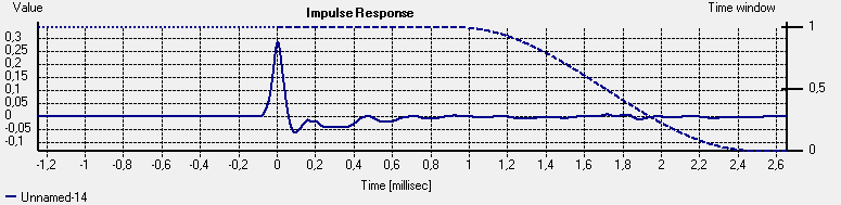
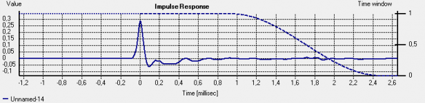
Now, here's the impulse measurement, I zoomed in a bit to make it clearer.
What can one read from this??
This is just what was in the impulse window.. how do I superimpose the gate on this??
Actually the window is right there. The tapering starts at 1ms, so the resolution is starting to falter under 1k. Not so hot. The region below 1k rapidly becomes unreliable d/t windowing.
I get it Ucla...
I thought the gating function was much sharper, but now I realise how this progresses up in the frequency range...
By the way, that was the impulse response with gating at around 700 Hz..
Perhaps 350 Hz gating can still be of some value if one can live with some (1dB) ripple?
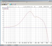
Now, I ran a baffle simulation, and here's the result
This seems to confirm what you said, that there is a hump just below 1k..
But again, the real-life magnitude of that hump depends on the in-box response of the driver..
Hmm.. seems like that mission to go set up in that warehouse is forcing it self..
And by the way.. since we got in to the pulse response.. does that plot say anything meaningfull about my loudspeaker ? I'm instinctively thinking "transient response" and such here...
I thought the gating function was much sharper, but now I realise how this progresses up in the frequency range...
By the way, that was the impulse response with gating at around 700 Hz..
Perhaps 350 Hz gating can still be of some value if one can live with some (1dB) ripple?
Now, I ran a baffle simulation, and here's the result
This seems to confirm what you said, that there is a hump just below 1k..
But again, the real-life magnitude of that hump depends on the in-box response of the driver..
Hmm.. seems like that mission to go set up in that warehouse is forcing it self..
And by the way.. since we got in to the pulse response.. does that plot say anything meaningfull about my loudspeaker ? I'm instinctively thinking "transient response" and such here...
Attachments
Well,
After the issues and limitations identified with my measurement set-up, I've decided to move out of my cosy but inadequate living room to something more appropriate.
This Saturday, I'm taking the stuff over to work for setting up in one of the workshop halls.
The limiting factor there will be how high above the floor I can get, but I think 2m should be possible to achieve, and the hall is more than spacious enough to get lots more than those 2m in any other direction.
Obviously, this will be totally impractical when the time comes to do tune in x-over and compensation, but if I have a good baseline, I hope it will be possible to "see" subsequent measurements through this when continuing back home again.
I'm taking the stuff over to work for setting up in one of the workshop halls.
...
The limiting factor there will be how high above the floor I can get, but I think 2m...
Great. 2m equals a 11.6ms (2m+2m) reflection free impuls resonse and a lower limit of 1/0.0116s ≈ 90Hz.
Best, Markus
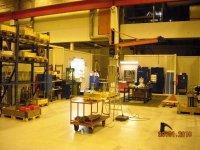
Finally, Saturday is here, and I've just come back from work where I did a new measurement set-up.
I figured it was well worth to heed the advice given about the inadequacies and uncertainties in connection with my living-room set-up. Considering the effort and investment made so far, it would be kind of stupid not to spend half a day trying to get the best possible measurements as a foundation for further work!
I managed to get the loudspeaker and mic about 230 cm up from the floor, which is a significant improvement to the measurement set-up I had in my living room.
The one thing I'm a bit wary about, is the aluminum pillar I used to get the loudspeaker up from the folding ladder I used, but we'll see what the measurements look like!
Also, the trolley I put the mic-stand on could have contributed with some garbage..
Attachments
Looks good! Try to cover the mike and loudspeaker stands with acoustic foam (= open cell foam) or fiber glass.
Best, Markus
Best, Markus
Markus,
Unfortunately, I didn't have foam or fiber available, nor any practical means of attaching it.
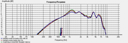
Initially, I made 3 on axis measurements, one at 40 cm (blue), one at 100 cm (red), and one at 190 cm (green). None of these dimensions are 100% exact as it was a bit tricky to measure distance exactly considering the height of the set-up.
The first thing that struck me, was the t HolmImpulse gated the measurements only 100Hz or so lower than at home. I suspect some reflections from the improvised set-up paraphernalia might have caused this.
The measurements below are shown with the initial gating and normalised in level to compensate for varying measurement distances.
What is also noticeable, is that the 100 and 190 cm measurements had a more pronounced peak at around 1k. Could this be that the mic picked up more of the "baffle step peak" caused by the aluminium pillar further out??
Unfortunately, I didn't have foam or fiber available, nor any practical means of attaching it.
Initially, I made 3 on axis measurements, one at 40 cm (blue), one at 100 cm (red), and one at 190 cm (green). None of these dimensions are 100% exact as it was a bit tricky to measure distance exactly considering the height of the set-up.
The first thing that struck me, was the t HolmImpulse gated the measurements only 100Hz or so lower than at home. I suspect some reflections from the improvised set-up paraphernalia might have caused this.
The measurements below are shown with the initial gating and normalised in level to compensate for varying measurement distances.
What is also noticeable, is that the 100 and 190 cm measurements had a more pronounced peak at around 1k. Could this be that the mic picked up more of the "baffle step peak" caused by the aluminium pillar further out??
Attachments
Now, the next thing I Need to figure out, is what I actually gained from the new measurements compared to what I got in my living room.
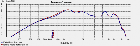
First I compared on-axis at 1m from home and in the workshop with the same gating.
The red curve is from the workshop, and the blue from home.
Not a great deal of difference, the workshop measurement is perhaps a bit smoother.
But these curves are still with the relatively short gate time, what will happen when I try to increase the gate time?
Will I be able to benefit from the greater surface-distances in the workshop??
Attachments
Last edited:
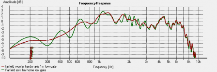
Here is the same measurement with a longer gate time.
For the workshop measurement, ripple gradually increased as I lengthened the gate time, up to a point where it didn't increase and I only got more low-end extension.
The home measurement got progressively worse as I increased the gate time to match that of the workshop measurement.
Obviously, the green curve is the home measurement with the shorter surface-distances.
Looks like I gained something, but the red curve is far from smooth.. how good was the measurement really?
Attachments
Last edited:
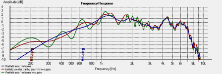
Now, in order to do a "reality check" on the workshop measurement with the longer gate time (red), decided to compare it with the raw measurement smoothed at 1/3 octave (green).
The blue curve represents the same measurement with the shorter gate time.
The blue curve represents the same measurement with the shorter gate time.
Attachments
Last edited:
excellent thread!!
I second that!
Are you going to go back and do off-axis in the workshop? Any plans on distortion measurements? Again, thanks for taking the time to document and work through these issues for the greater good.
Ostensibly, the benefits of measuring reflection-free at 2m vs. 1m are 1) better integration between the drivers, and 2) resolution of frequencies an octave lower. Did those occur, and was it sufficiently worth the effort to warrant doing this routinely?
What is your acoustic crossover frequency, that we may discern the driver integration element in the results?
What is your acoustic crossover frequency, that we may discern the driver integration element in the results?
Last edited:
- Status
- Not open for further replies.
- Home
- Loudspeakers
- Multi-Way
- Measurement approach, 2-way closed box