The cost for the PCB's is 10x11$ or 25x7$ (ex mail cost) so add you name to the next list if you want a board (or hom many).
PCB-buyers-list
==========
FdW 3x
Piersma 1x
Mark Johnson 2x
PCB-buyers-list
==========
FdW 3x
Piersma 1x
Mark Johnson 2x
The actual price of the boards is now 12.28 Euro, slightly higher as stated before, but now the price includes the shipping cost charged to me by the board supplier. The board have been ordered today and will be produced in 6 day, when they arrive I will send pm's with payment details (PayPal).
The cost for the PCB's is 10 x 12.28 Euro (ex mail cost), add you name to the next list if you want a board or boards.
P.s. Copy this message (copy/past) and add your forum-name and number of boards at the end.
PCB-buyers-list
==========
FdW 3x
Piersma 1x
Mark Johnson 2x
Joachim Gerhard 1 x
The cost for the PCB's is 10 x 12.28 Euro (ex mail cost), add you name to the next list if you want a board or boards.
P.s. Copy this message (copy/past) and add your forum-name and number of boards at the end.
PCB-buyers-list
==========
FdW 3x
Piersma 1x
Mark Johnson 2x
Joachim Gerhard 1 x
Last edited:
I'm in for two:
PCB-buyers-list
==========
FdW 3x
Piersma 1x
Mark Johnson 2x
Joachim Gerhard 1 x
PH104 2x
PCB-buyers-list
==========
FdW 3x
Piersma 1x
Mark Johnson 2x
Joachim Gerhard 1 x
PH104 2x
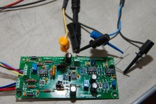
I did build one all parts did fit nicely, tomorrow I will do the electrical testing of the bord (i'm sure it is fine).
But.. one [tiny] problem: I do not have any testable amplifier (at this moment), so, for me, testing this board has to wait at the least 2 weeks (sorry for that 🙁). I'll be back 🙂
But.. one [tiny] problem: I do not have any testable amplifier (at this moment), so, for me, testing this board has to wait at the least 2 weeks (sorry for that 🙁). I'll be back 🙂
First result, U1 oscillated and needed a small compensation capacitor. The capacitor C2, in the schema 0pF, has been populated with a 10pF mica capacitor to stop the oscillations.
Using R15: The offset of U1, was adjusted to within 10uV, that seems adequate.
Using RGb: The gain of U2 was adjusted to 1Vdc at VRaw (for a 50mA current in 2 x 1 Ohm between inputs Red, Yellow and Blue [Yellow connected to ground]).
Using R10: The output offset at VBias was adjusted to zero (with inputs Black, Yellow, Red and Blue all connected together).
The circuit passed all tests that I can do at this moment, next measure some bias in a real amplifier 🙂
Last edited:
@Mark, Phil,
Now lets see what they do 🙂 (there is still no amplifier available here).
Regards,
Frans.
Now lets see what they do 🙂 (there is still no amplifier available here).
Regards,
Frans.
I'm afraid this is about eighth or ninth priority for me; won't get stuffed and soldered for quite a while.
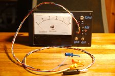
Just so you all know, the device works no problem 🙂
In a few days I will publish some measurement experience data.
In a few days I will publish some measurement experience data.
This here is a BOM in PDF and Excel format, there are no order numbers for any supplier but even without it may be useful 🙂
Other useful files are here Measure DC-bias in a operating class AB (or A) amplifier
Other useful files are here Measure DC-bias in a operating class AB (or A) amplifier
Attachments
- Status
- Not open for further replies.
- Home
- Amplifiers
- Solid State
- Measure DC-bias in a operating class AB (or A) amplifier