Initially I thought the tube stage had a 1.5 voltage gain (check my first posts...).
When Cerrem popped up he made me have doubts, and as I have an MC275 nearby why not take the effort and do the measurements?
Cerrem at least is the only one here who apparently has experience with these amplifiers and their transformers; all other guys (sorry) seem to have their knowledge from the books.....
At least no one else comes up with real measurements.
When you say, smoking-amp, that the 1.5 voltage gain is "observable in all the documentation and articles written including those by Mac", I wait for a link to one of those for a confirmation.
The "last man standing thinks he wins the argument" argument does not hold; I actually feel being corrected wrt to the voltage gain of this output stage, and I am willing to admit I was wrong.
Unless the 1.5 fans come up with real measured evidence, I regard the output stage to have a 0.75 voltage gain.
When one tube is pulled out I don't see the follower able to drive the output transformer.
When one tube is removed, the remaining follower has strong N Fdbk to try and maintain the same gain, but is severely stressed.
All the other posters who were providing support for the 1.5 gain have dropped out from exasperation. I have never seen a single article that supported the 0.75 gain. Just actually read ANY of the myriad references that were provided earlier.
Putting two equal gain circuits in parallel (the two output tubes with drivers), each with 1.5 gain, does not reduce the gain by half. That should be a show stopper right there. Almost EVERY concept presented here has been severely flawed. It is prohibitively impossible to straighten out such a mess. You all have shown how tube mythology is developed and enshrined. Just go over to the SE OT thread now and lap up the no hysteresis fantasy too.
I plan to stay clear of tube audio from now on. Nothing but BS.
Sayonara. Closing account.
- removing one tube does not change the voltage gain of the output stage, and this one tube voltage gain is about 1.5 (what a cathodyne stage is supposed to do);
But 4 tubes are driving the primary windings and you only removed 1 of them. I don't see what this is supposed to prove WRT gain.
- with both tubes, the normal situation, the voltage gain of the tube stage is about 0.75.
How are you defining gain? The ratio of which voltages?
All of my discussions so far have been centered on the Unity-Coupled output stage alone, without the driver circuitry taken into account. In my amp, the driver is not bootstrapped and does not drive the output transformer at all.
For me, the correct way to define gain (and I think this is where a lot of us are getting sideways in this discussion, arguing about gain without first agreeing on what two voltages we are using to compute it) is to see that one tube conducts for a little over half of the output cycle and swings a little less than B+ into the winding. When a tube is cut off, it doesn't do anything.
So one tube in my amp (460V B+) swings down from there to about 60V, working into its own plate and cathode 1/4 winding (1/2 of plate winding and 1/2 of cathode winding). One tube swings about 400V peak, which is divided between the two 1/4 windings.
When the signal swings the other way, that tube doesn't contribute much to output because it spends most of the AC cycle in cutoff. So the way I look at it, each tube contributes ~half of the AC voltage swing for the primary, which is 800Vpk-pk.
The drive required in my amp to produce this swing is ~230V peak per side (referenced to GND), so if you measure differentially at the two grids, you will see 920Vpk-pk of signal there. If this is how you define the gain calculation, so be it.
The big problem with defining gain this way, of course, is that if you analyze a push-pull cathode follower output stage with a 460V B+, you will quickly see that it has half of the gain of the Mac output stage (it will take 1840V peak differential swing to drive to clipping). So if you are saying that a UC output has a max gain of 1, you are also saying that a CF output stage has a max gain of 0.5. Look at them both carefully, analyze them, and you will see that the UC has twice the Va-k swing that the CF has per volt of input. Be consistent and there is an obvious difference of a factor of 2. I think it is silly to come up with a definition of gain that has a CF with max gain of 0.5. If you do this, you are making a decision to be on a different page than most everyone else, and for no good reason.
I share smoking-amp's frustration. I miss the old threads with Michael Koster, Ken Peter, etc.
Last edited:
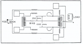
"Figure 7 also shows that some direct -coupled negative voltage feedback is used . It will be seen that since half of the load is in the cathode and half of the load is in the plate, as before mentioned , almost the entire gain in this final stage is lost by virtue of the feedback resulting from this method of loading. Additional feedback is achieved by connecting suitable resistors between the cathodes of the output tubes and the cathodes of the phase inverter stage."
Attachments
All the other posters who were providing support for the 1.5 gain have dropped out from exasperation. I have never seen a single article that supported the 0.75 gain. Just actually read ANY of the myriad references that were provided earlier.
First you point to articles supporting for the 1.5 gain and as expected you can not provide a link to confirm this, and then you have never seen a single article supporting the 0.75 gain 🙄🙄🙄
The "dropped out others" do not seem to be interested anymore as maybe reality is different from what they thought.
How are you defining gain? The ratio of which voltages?
The ratio of the input voltages at the KT88 grids and the voltages at the primaries of the output transformer (2 x plate; 2 x cathode), all referenced to ground.
First you point to articles supporting for the 1.5 gain and as expected you can not provide a link to confirm this
McIntosh themselves says the output stage has more than unity gain, yes less than normal due to the method of loading and feedback but still more than unity gain.
www.cieri.net/Documenti/Schemi/McIntosh - Description and analysis of a new 50 watt tube amplifier circuit.pdf
Logically even if you don't understand how the circuit works why would you not at least believe it when McIntosh puts out an article and says it plain as day in the analysis of the circuit.
Your link does not work but nevertheless I re-read this article.
Please point me to the paragraph where McIntosh says the output stage has more than unity gain, etc.
I don't find it.
Please point me to the paragraph where McIntosh says the output stage has more than unity gain, etc.
I don't find it.
http://www.cieri.net/Documenti/Sche...s of a new 50 watt tube amplifier circuit.pdf
The last paragraph on page four;
"...almost the entire gain of this final stage is lost by virtue..."
The wording indicates there is still gain but less than normal.
The last paragraph on page four;
"...almost the entire gain of this final stage is lost by virtue..."
The wording indicates there is still gain but less than normal.
Right, but read well: "almost the entire gain of this final stage is lost by virtue of this method of loading....".
The method of loading is equal load in the plate and cathode circuit of both tubes which gives a real gain of about 1.5 for each tube. McIntosh refers to a standard push-pull output stage when stating "the entire gain of this final stage is lost....".
However, in the output transformer these 1.5 gains do not sum (which Cerrem already pointed out).
In the same article you will read that the secondary sees halve of the step down ratio in the output transformer compared to a normal push pull output stage.
In the MC275 the winding ratio of the plate-plate and cathode-cathode primaries are both 8:1 wrt the secondary. These primaries are in parallel, not in series.
We measured "back": 2,3V at the speaker terminal x 8 (plus transformer loss) gives 20V total primary swing with 30V grid-grid swing.
We concluded the voltage gain therefore to be 20 : 30 = ~ 0.67.
Last edited by a moderator:
In the MC275 the winding ratio of the plate-plate and cathode-cathode primaries are both 8:1 wrt the secondary.
That's where you are going wrong, in the paragraph before the one I referenced it states: "...there is inherently a 16:1 advantage in this circuit.."
Which makes sense to what you are measuring.
2.3 * 16 = 36.8
36.8 / 30 = 1.226
So the final stage has a gain of 1.226
You don't read in the right context!
That same paragraph: "Compared to a standard push-pull output stage the unity coupling design has a 4:1 impedance reduction between the tubes reducing the effects of stray capacitances by a factor of 4 (good for bandwidth and phase shift)".
Furthermore (now quoting the article word by word), "since the two primaries look like one winding to the secondary, the effective turns ratio has been reduced by a factor of 2 to 1 between primary and secondary. This results in a 4 to 1 coupling advantage compared to a standard push pull stage.
Since both the shunting capacitance impedance advantage of 4 and the coupling advantage of 4 occur simultaneously, there is inherently a 16 to 1 advantage in the unity coupling circuit over a conventional push pull circuit".
Your "16:1 advantage" has nothing to do with the winding ratios!
Last edited by a moderator:
First you point to articles supporting for the 1.5 gain and as expected you can not provide a link to confirm this, and then you have never seen a single article supporting the 0.75 gain 🙄🙄🙄
The "dropped out others" do not seem to be interested anymore as maybe reality is different from what they thought.
It's 1.5-1.7 for most output tubes and transformers, 2 ideally. Gm*R_load/(1+0.5*Gm*R_load).
Are you forgetting that both output tubes are being driven?
SpreadSpectrum built one and confirmed this in this thread.
Almost 10 years ago, bricktop and I built one and confirmed the same, with similar overall results.
If the gain were 0.75, a Mc amp would not achieve full power. Nor would ours; we designed it based on the theory-predicted gain and it worked as expected.
smoking-amp's exasperation theory is correct. 😉
First you point to articles supporting for the 1.5 gain and as expected you can not provide a link to confirm this, and then you have never seen a single article supporting the 0.75 gain 🙄🙄🙄
The "dropped out others" do not seem to be interested anymore as maybe reality is different from what they thought.
Nope, it is just that it has become tedious to watch you and others ignore the fact that a CF takes twice the drive as the UC to produce the same output voltage swing.
It is certainly possible to define gain such that the UC has a gain approaching 1, but using that definition means that a CF output stage has a max gain of 0.5. I think that using such a definition is silly.
What do you want me to say: sorry I forgot both tubes are driven? 😀
OK let's try another approach, based on RMS voltages as specified by McIntosh.
The MC275 is specified to deliver 75W into 4, 9 and 16 ohms.
Let's take the 9 ohm tap; so 26VRMS must be delivered into that load for 75W.
In a former post I gave the voltage and resistance chart which comes along with the MC275 manual. The AC Volts values at rated output is important.
For rated output power the AC voltage at both KT88 grids is specified to be 149V.
Correct me if I am wrong, but I think this is peak voltage, and the RMS voltage is (2x149/2.83) = 105VRMS.
So at rated output power each KT88 has 105VRMS at it's grid, the total for both tubes (differential) being 210VRMS. Right? If not please correct!
So for 26VRMS at the output of the amplifier we need 210VRMS at the power tubes grids.
The step down in voltage from 210 to 26 is a function of tubes gain and output transformer step down ratio.
The output transformer has two identical (and bifilar wound) primaries for the plate and cathode circuit, both with an 8 : 1 step down ratio wrt the 9 ohm tap. In the article(s) it is clearly stated that the secondary sees these primaries as a single one, with this 8 : 1 ratio.
The RMS voltage swing at the primaries of the transformer therefore must be 26 x 8 = 208VRMS; let's say some 220VRMS because of losses in the transformer.
So, 210VRMS at the grids and 220VRMS at the primaries would give us a voltage gain of the tubes of about 1.
Instead of coming up with out of context quotes from the articles I would appreciate if someone would take the effort to check my calculation so we might come to some sort of conclusion.
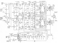
See the MC275 schematic for additional information.
OK let's try another approach, based on RMS voltages as specified by McIntosh.
The MC275 is specified to deliver 75W into 4, 9 and 16 ohms.
Let's take the 9 ohm tap; so 26VRMS must be delivered into that load for 75W.
In a former post I gave the voltage and resistance chart which comes along with the MC275 manual. The AC Volts values at rated output is important.
For rated output power the AC voltage at both KT88 grids is specified to be 149V.
Correct me if I am wrong, but I think this is peak voltage, and the RMS voltage is (2x149/2.83) = 105VRMS.
So at rated output power each KT88 has 105VRMS at it's grid, the total for both tubes (differential) being 210VRMS. Right? If not please correct!
So for 26VRMS at the output of the amplifier we need 210VRMS at the power tubes grids.
The step down in voltage from 210 to 26 is a function of tubes gain and output transformer step down ratio.
The output transformer has two identical (and bifilar wound) primaries for the plate and cathode circuit, both with an 8 : 1 step down ratio wrt the 9 ohm tap. In the article(s) it is clearly stated that the secondary sees these primaries as a single one, with this 8 : 1 ratio.
The RMS voltage swing at the primaries of the transformer therefore must be 26 x 8 = 208VRMS; let's say some 220VRMS because of losses in the transformer.
So, 210VRMS at the grids and 220VRMS at the primaries would give us a voltage gain of the tubes of about 1.
Instead of coming up with out of context quotes from the articles I would appreciate if someone would take the effort to check my calculation so we might come to some sort of conclusion.
See the MC275 schematic for additional information.
Attachments
Last edited by a moderator:
OK let's try another approach, based on RMS voltages as specified by McIntosh.
I don't think we need a different approach, especially when the straightforward approach is so simple.
A class B UC amp has one tube working into two quarters of the primary in series for ~half of the AC cycle.
Similarly, a class B push-pull CF amp has one tube working into two quarters of the primary in series for ~half of the AC cycle.
The CF amp will take twice the input voltage to produce the same AC swing on the two quarter-primary segments.
Do you agree or disagree?
Speadspectrum,
I checked your unity coupling design for a comparison.
Output power of your amp is about 40 W, 8 ohm load, right?
That is 18 VRMS.
The output transformer is 6k4 total primary wrt 8 ohm load, that is 1k6 in the plate circuit and 1k6 in the cathode circuit.
Your KT88's have each some 100VRMS on their grids for a total swing of 200VRMS to reach clipping.
The output transformer has an effective ratio of 14,14 : 1, so voltage swing at the primaries is some 250VRMS.
This is a voltage gain of about 1,3 when we take a bit of transformer loss into account.
The major difference with the MC275 is IMO that your amp has quite some higher primary impedance (6k6 opposed to 2k3) so voltage gain of your tube stage will be higher.
That does not compare too badly with the gain of ~ 1 I calculated above for the MC275.
Your opinion?
Agree.Do you agree or disagree?
Important is that the primary impedance of the MC275 output stage is very low at 2k3.
I don't measure a 1.5 voltage gain there, it is nearer to 1.
Loading a KT88 CF output stage with 2k3 would result in considerable voltage loss as well, being no more than some 0.6 in my estimation.
Last edited by a moderator:
Interesting to compare is this design by Lockhart back in 1956 and based on the Frank McIntosh unity coupled design (1948):http://www.tubebooks.org/books/lockhart.pdf
Please note the composite load for the output stage is 6k for a pair of 6L6's, and that is nowhere near the 2k3 of the MC275.
I am tempted to repeat my earlier remark that the MC275 is designed to squeeze the maximum out of a pair of KT88's in a unity coupling circuit, based on very lowish load impedance and a high amount of feedback to compensate. Sound quality was rather disappointing in my set up with Yamaha NS1000 loudspeakers. The unity coupling design however is intruiging, and I am sure better unity coupling amplifiers can be made. Did you have the chance to compare Speadspectrum?
In the original article about the MC 50 amplifier Frank McIntosh and Gordon Gow state:" It will be seen that since half of the load is in the cathode and half of the load is in the plate, as before mentioned, almost the entire gain in this final stage is lost by virtue of the feedback resulting from this method of loading."
Almost can ONLY mean: gain>1. It is OBVIOUS that this cannot be a fixed value because it also depends a little on the operative conditions.
It will be on the low side when class B with low primary load, it will approach 2 when class A with optimum load.
McIntosh was only interested in class B as he had just solved all typical problems of class B operation. From his perspective class A and even class AB were just a waste.
Arguing about the gain of this type of power stage has become quite boring.
Last edited:
- Status
- Not open for further replies.
- Home
- Amplifiers
- Tubes / Valves
- McIntosh bifilar output stage test proof