There are a lot of people that say they can wind the mac OPT but went put to the task they can't do it.I suppose if they were trained to do it they could but I have taken a Mc225 over to Phil at Heyboer and then I sent it to Maine transformer and both said we can't do it..If there is someone that will do it and do it right in the 450 dollar range,let me know and I will give them a try..It's a just a spare one have being I have a lot of mac tube amps but I would love to have this spare because the writing on it is perfect.I'm in hurry so they can take their time.
I did, and even better than original ones 🙂
Frank McIntosh's 1949 paper is in an Audio Anthology I'm pretty sure, and well worth reading. If not available on line, I can scan and post it. Don't think he'll mind.
It's not, so if you could, that would be great. The Crowhurst analysis is, and was linked earlier.
Set up a measurement with a certain input voltage (I really mean at the input of the amplifier) and measure the output voltage at the secondary into 8R. Then, leaving everything as is, disconnect the plates from the transformer and connect them to the supply. That's the true pentode cathode follower (yes, you need to drive the screen grids the same way). Now measure again the output voltage and see how much you get. I "guess" this is somewhere between 1.5-2 times lower. As nothing else has changed it follows that the MAC output stage does have a voltage gain regardless of the way you want to look at it.
For the pentode cathode follower stage the driver has to provide a bit more than the full output voltage instead of just about 1/2 of it. It makes all the difference in the world because for high power stuff numbers start to become really high. This is the reason why cathode followers (pentode, triode or ultralinear) are not common otherwise they represent the best kind of output stage in terms of properly driving real reactive loads. The MAC output stage will still behave like a pentode. In particular, if the real load drops and is reactive its driving ability will be poor regardless of its Zout. In fact the power delivery into such lower and reactive load will reduce drastically and distortion will increase a lot. So one cannot use any speaker.....
P.S.
I forgot to say that, in order to have the same conditions, the last voltage amplifier should not be bootstrapped and independent of the output stage operative conditions. Its max output capability is not important as the comparison can be done at any output level.
and put all that added stress on the driver when if the output stage can double the gain and be done with it. I realize it looks like a cathodyne phase splitter which does have a 2 to 1 gain but I think there are things going with this circuit due to the output trafo that we are missing..I mean clearly you could see where the Dyna did step the up the voltage and even you think it was measured wrong,there should still be some type of 2 to 1 ratios with one of the numbers and I don't see that..
I didn't read down the thread, stopped here.
The answer for the bootstrapping is to increase the available drive swing at the grids of the output tubes. In the case of an amp like the MI-200 there are few choices other than the bootstrap since the swing required exceeds the max plate voltage for potential driver tubes.
In lower power circuits, yes the plate voltage for the driver *might* be jacked way up and you might get by. But remember these are AB2 not AB1 amps.
_-_-
I agree with SpreadSpectrum.
Besides, if the output stage of the MAC didn't have any voltage gain that configuration would just be silly because a power cathode follower would be much easier, economical and would have even better performance in terms of driving difficult loads. How could one possibly get a patent out of such a silly idea???
A few reasons.
1) No one had done it before.
2) it solves a few problems, most notably rather improved bandwidth and much easier to wind output iron (in production) and the pesky crossover notch distortion in class B issue
If you check Radiotron, you will see that at the time there were a great many "cathode coupled" output stage schemes. There's a good reason that you don't see any of the others, and that none of them went very far past their initial introduction, if that far.
Correction - The 50-W2 and the MI-200 are AB2. The Mc30/60 etc are not, iirc. Sorry about that.
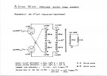
Below is the drawing of the measurements we did yesterday.
When there is agreement on the composite load impedance to be 2k3, my feeling is that we are all suckers, and cerrem is right in his statement that the tubes do not provide voltage gain (output transformer has effective 8:1 step down ratio wrt the total AC voltage swing).
Correct me if I am wrong!
To 45: for a mere cathode output stage to have the same load impedance a 16:1 step down output transformer would be needed, which would require even more voltage swing at the tube grids. I guess the designers at McIntosh were clever enough to know that.
Besides, and that was the aim of the unity coupling design, in a cathode output stage the notch distortion appearing when the amplifier leaves class A would not be "cancelled" the way it is done by unity coupling.
In case of pure class A and enough available voltage swing there is nothing against a cathode follower output stage amplifier though.
To cerrem: I really wound replacement output transformers for the MC275; done on two stacked c-cores (SU75b) with two coils (one on each leg). These were bifilar wound with the same winding ratios and perform flawlessly. When able to wind bifilar these transformers are not more difficult to do well than any other output transformer. Unlike the original output transformer I applied isolation between the primary and secondary sections; the original transformer had no isolation between primaries and secondaries so by touching the loudspeaker terminals only the wire enamel provided the isolation of the high plate voltage which did not help to feel safe...
Attachments
re: Horilka
"It's a class B (AB) amplifier. What happens when 1 tube is cut off when they are in serie?"
The cathode and plate windings are in series (but for each tube only). The tubes are not in series, the tubes are in parallel. That's why the amp can be biased for any of class A, aB, B1, B2.
------
The Mac OT was a work around of the ElectroVoice Circlotron patent. At the time, EV was using two power supply windings on the same power xfmr (so high common mode C), so the Mac OT outperformed it. Today it is easy to construct A Circlotron Amp using cheap industrial split bobbin power xfmrs with just 50 pF common mode, and so exceed the Mac performance.
------
re Pieter T
That diagram is clearly an 8 to 1 winding for each tube, but Cerrem will be telling us it is 4:1 due to "parallel" windings.
-
Last edited:
Keep in mind that you can not use the traditional plate curves....
Indeed, you need to apply the procedure outlined in O. H. Schade's Beam Power Tubes to derive plate curves for the stage. This isn't rocked science.
I was simply pointing out that if you attempt to draw a load with the assumption that gain is less than one, you will notice that you only get halfway to saturation (which is not what is actually happening).
Note that notch distortion and crossover distortion are not the same thing. The function of the unity coupling is to eliminate the former.
The cathode and plate windings are in series (but for each tube only). The tubes are not in series, the tubes are in parallel. That's why the amp can be biased for any of class A, aB, B1, B2.
-
Do you agree with Chris, post # 113?
Note that notch distortion and crossover distortion are not the same thing. The function of the unity coupling is to eliminate the former.
We know that Stuart; the notch distortion is a combination of a distorted waveform and malfunction of the output transformer.
re; Pieter T
Crowhurst Twin
We will need another year to discuss that one!
Just putting caps between the Twin OTs will make them perform as well as the Mac OT. So really no need to wind a Mac OT. (see Elliptical version below)
"Do you agree with Chris, post # 113?"
No, that's who I was reponding to above. Each winding section is 1/2 the primary for a tube, not 1/4.
----
There is also the Elliptical Twin, which is more practical to drive:
-
Attachments

Last edited:
@pieter t - referring to the test schematic and the gain calculation, again may I ask how about the cathode winding, that's the other half of the load, no? Where does it show up in the gain calaculation?
That's the whole point jazbo!
In Cerrem's opinion, because the plate and cathode windings are in phase for the AC voltage, these two values don't add.
In Cerrem's opinion, because the plate and cathode windings are in phase for the AC voltage, these two values don't add.
"Do you agree with Chris, post # 113?"
No, that's who I was reponding to above. Each winding section is 1/2 the primary for a tube, not 1/4.
On the plotting of a load line for Mac, one can just do the conventional plot using the correct loading (cathode and plate windings in series). Then obtain the usual distortions from the plot. Multiply those distortions by the factor (actual grid drive, g1 to k)/(apparent grid drive, g1 to ground) to get the final distortion figures. The graph distortions just get diluted out by the Fdbk.
apparent grid drive = actual grid drive + V swing on the cathode winding
That's the whole point jazbo!
In Cerrem's opinion, because the plate and cathode windings are in phase for the AC voltage, these two values don't add.
Please bear with me, but on the drawing the plate and cathode voltage have the opposite phase, i.e., they are out of phase not in phase.
Please bear with me, but on the drawing the plate and cathode voltage have the opposite phase, i.e., they are out of phase not in phase.
As they should be. They are driving opposite ends of the total primary.
(so just add the magnitudes for the gain calculation) (or use a differential measurement between cathode and plate)
Last edited:
We know that Stuart; the notch distortion is a combination of a distorted waveform and malfunction of the output transformer.
I know you do, but I saw someone else conflate those terms- that can be misleading and confusing.
- Status
- Not open for further replies.
- Home
- Amplifiers
- Tubes / Valves
- McIntosh bifilar output stage test proof