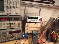
Ok I said I would do this test and I did..I talked to Doc Hoyer and he said you want to measure the total circuit of both output tubes because that's its function..The Fluke is measuring the RMS voltage in across both input grids and you can see that it is 325vRMS.There is 218.32vRMS across the plates which is being measured by the Instek and this is with a 1v signal coming in from the generator.In order for this output circuit to be a voltage amplifier,it would would have to increase the voltage at the plates vs the input grids as I will show you it does not increase.
On the Dynaco VTA70 we have 38.7vRMS going in across the grids and 673vRMS coming off at the plates with the same 1v input signal being used.In this circuit,it clearly does increase as a voltage amp should.
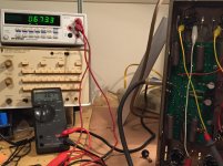
The last test I did was measure the output at the speaker terminals of the Mc30s without the 6L6gcs installed and it was 15.8v and when I put the output tubes back in,it went up to 18.3v but again,that is a marginal gain and it is due to the added current..All the tests were performed with the output tubes installed..I used 1v because I didn't need to drive the amp to full power for the test.
If any of you have Macs and do this test,you will come up with the same type result.
On the Dynaco VTA70 we have 38.7vRMS going in across the grids and 673vRMS coming off at the plates with the same 1v input signal being used.In this circuit,it clearly does increase as a voltage amp should.
The last test I did was measure the output at the speaker terminals of the Mc30s without the 6L6gcs installed and it was 15.8v and when I put the output tubes back in,it went up to 18.3v but again,that is a marginal gain and it is due to the added current..All the tests were performed with the output tubes installed..I used 1v because I didn't need to drive the amp to full power for the test.
If any of you have Macs and do this test,you will come up with the same type result.
Attachments
Last edited:
But how about the cathode winding? They are also a part of the output stage.
It's splits the load but it doesn't matter because you get the same reading on the cathodes as you do on the input grids even without the output tubes installed. The point is for this would have to be a voltage increase at the plates and there is not but on the Dynaco there is.Doc Hoyer knows these circuits like the back of his hand.He was friends with Frank McIntosh and Sidney Corderman and with Stu Hegeman over at HK..I think he knows what he's talking about.
Last edited:
Both the plate AND the cathode windings are coupled to the output via the OPT's core, so where does the energy from the cathode winding go? It can not just disappear, can it?
As I told you,when you measure the voltage on the cathodes with no output tubes installed,it 325rms on the grids and the same identical voltage is on the cathode terminals.So that voltage is already there even before you install the outputs tubes .That voltage probably stays on the cathodes and works as a cathode follower to help develop the added current for the output stage..I'm guessing there but I can ask Doc..Here is the thing,if we split the 325v that gives you 162.5 and if we were to double the 325 or double the 162.5 as a 2 to 1 gain,it still doesn't come out to numbers shown on the plates. All the voltage gain is done in prior stages and that's why we have such a high number on the MACs G1 grids and on the Dynaco it is very low. Bottom line,you get same RMS voltage at G1 and the cathodes with or without the output tubes installed. If the output stage had a 2 to 1 gain,we wouldn't need to boot strap the driver because the output stage would take care of stepping up the voltage as it does in the Dynaco.
Last edited:
with no output tubes installed,it 325rms on the grids and the same identical voltage is on the cathode terminals.So that voltage is already there even before you install the outputs tubes .That voltage probably stays on the cathodes and works as a cathode follower to help develop the added current for the output stage..I'm guessing there but I can ask Doc.
It would be interesting if your Mr. Doc could chime in as he seems to be your guru.
One thing however is clear: you have no clue of how these unity coupling designs work, and you apparently do wrong measurements.
Measuring voltages at tube terminals without installing them? 😀🙄
The MC275 output stage acts like a catodyne phase splitter with equal loads in the plate and cathode circuit.
Unloaded this would give a voltage gain of 2; loaded in the practical case of the amplifier the voltage gain is about 1.5 as I measured already a couple of years ago (MC275 with shorted output transformer as discussed earlier at this forum).
Last edited by a moderator:
Actual Tube Voltage Gain = (Vplates + Vcathodes)/(Vgrids - Vcathodes) = (436.6/106.7) = 4.09
Apparent stage gain (relative to drive signals) = (Vplates + Vcathodes)/(Vgrids) = 1.34
You cannot use just the plate voltage, this is not a grounded cathode stage. Some confused gurus I think.
Apparent stage gain (relative to drive signals) = (Vplates + Vcathodes)/(Vgrids) = 1.34
You cannot use just the plate voltage, this is not a grounded cathode stage. Some confused gurus I think.
I have worked on a lot of these amps in the past and owned a pair of MC-30 for many years and can confirm both pieter t and smoking amp comments are consistent with my experience.
One thing however is clear: you have no clue of how these unity coupling designs work, and you apparently do wrong measurements.
You obviously didn't read what I said. I did this both ways for verification to which voltages exist on the output tube grids and cathodes with and without the output tubes being installed. The actual measurement was taken with the output tubes installed on both amps.
Last edited by a moderator:
Both the plate AND the cathode windings are coupled to the output via the OPT's core, so where does the energy from the cathode winding go? It can not just disappear, can it?
It acts like a CF more or less like an output stage of a preamp.
Nobody can seem to tell me why they bootstrap the driver and put all that added stress on the driver when if the output stage can double the gain and be done with it. I realize it looks like a cathodyne phase splitter which does have a 2 to 1 gain but I think there are things going with this circuit due to the output trafo that we are missing..I mean clearly you could see where the Dyna did step the up the voltage and even you think it was measured wrong,there should still be some type of 2 to 1 ratios with one of the numbers and I don't see that..
Actual Tube Voltage Gain = (Vplates + Vcathodes)/(Vgrids - Vcathodes) = (436.6/106.7) = 4.09
Apparent stage gain (relative to drive signals) = (Vplates + Vcathodes)/(Vgrids) = 1.34
You cannot use just the plate voltage, this is not a grounded cathode stage. Some confused gurus I think.
There are lots of gurus that think you can do it this way and if you can set up and amp and show me with the equipment to verify,I would be willing to listen. I measured the total product coming off the plates of the output stage and I saw a drop.There has to be some kind of voltage increase for it to be a voltage amp..This is why there is probably 50/50 argument on this subject amps because even Dave Gillepsie and Terry D'Wick both say it's not amplifying voltage..I think you guys might know who they are...The reason I trust Hoyer's opinion is that he is the only that I know of that can wind the Mac opts. I've been trying to get someone to do a pair of Mc225s for less than 550 each.
Last edited:
Please read a bit into this subject before blah-blahing the way you do now; there is enough to be found on the WWW. Try Pete Millets site for Alvin Lockhart's unity coupling design with a trifilar wound output transformer for a start because it is a simpler design wrt feedback and therefore easier to grasp, and googling the subject will give you the needed information.
As told before I had a MC275 here with a shorted output transformer; I completely dismantled this output transformer and know exactly how (badly) it was wound, the winding ratios etcetera.
Winding a new output transformer on a c-core (yes that was used by McIntosh in the good old days instead of the cheapo EI transformer which came with this "modern" MC275) gave rather better results.
If you can wind a couple C core trafos for my 275 I would be interested in that..My Mc60s have a double c core I believe.. I'll email Pete Millet and I get a lot of good info from him.. Do you have any logical idea why the driver would be bootstrapped if this can be achieved in the finals? This is why I think simple logic is being defied here because the measurement numbers just don't show this 2 to 1 ratio..
A read of Crowhurst's "Realistic Audio Engineering Philosophy" as well as his treatment in "Understanding Hifi Circuits" will clear up some of the fundamental misunderstanding of how that circuit works and what the AC voltages are. It's written in a very clear and understandable way. I'm pretty sure that the former reference is available somewhere on the internet, not sure about the second (but it's a book Mr. Samra ought to own).
First you should realize what McIntosh wanted to achieve with the MC275: to get as much low distortion power as possible out of a pair of KT88's.
One of the techniques they applied were split-loading the output tubes to lower their impedance; the low source impedance created this way is better able to drive a low primary impedance output transformer. I measured the p-p impedance to be some 2k.
By loosing voltage gain with split-loading more voltage had to be created in the input and driver stages.
Finally this high open loop gain was necessary to be able to apply overall negative feedback.
Applying these techniques they reached their goal: a high power tube amp with low distortion.
Soundwise however they are not the best IMO.
I have this book in hardcover but not the one you mention.
http://www.itermoionici.it/letteratura_files/Radio-Engineers-Handbook.pdf
http://www.itermoionici.it/letteratura_files/Radio-Engineers-Handbook.pdf
I measured the output trafo imp in one of my mac amps and I was using the Vo at the secondary divided by voltage in at the primary squared and then multiplied it by the 8 ohm impedance I was using..I did this at the cathode windings and the plate windings and what was feeding screens I believe and I'm going from memory but two of the windings were like 600 ohms and one was like 900 ohms. I put the variac across the plate windings and across the cathode windings when I did those numbers. It seems tho most of their tube power amps measure in a similar way..
The thing is you still don't have to bootstrap the driver to do that but I'm going to try some other measurements and see what comes up.
The thing is you still don't have to bootstrap the driver to do that but I'm going to try some other measurements and see what comes up.
Last edited:
- Status
- Not open for further replies.
- Home
- Amplifiers
- Tubes / Valves
- McIntosh bifilar output stage test proof