if that is the case then we have to make do with the information given in your post no.32....
we can continue this thru email.....
we can continue this thru email.....
hi,
ok, based on what i have read from the literatures, and inputs from you, here's what i have gathered:
1. tri-filiar windings for primary, 230 volts at full load of 75 watts
2. secondary feedback winding has the same turns as the 16 ohm secondary winding.
At 75 wattts output the coressponding outputs are as follows:
1. 16ohms, 34volts @ 2.2amps
2. 8ohms, 24volts @3.15amps
3. 4ohms, 17.3volts @ 4.33amps
so now turns ratio can be determined....
you want to use e-i 1 1/2 in stacked 3 inches thick...
i will use a flux density of about 55kilolines per square inch to be safe......
i will use 700cir mils per ampere to get wire sizes....
if preliminary data are correct then, i have the coil data, but i want to confirm that coils will fit the window....
Thanks,
My Nos. 6390895, 2806043.
You mention last time that 1-1/2 x 3.0 is not available. Where in manila i can get this?.
My Nos. 6390895, 2806043.
You mention last time that 1-1/2 x 3.0 is not available. Where in manila i can get this?.
if you want goss, you can go to dau, in pampanga, they might have them, maybe 1 3/4 in e-i...
silicon steel can be purchased in raon, deeco is one such store, cost is about 55pesos per kg..e-i 1 1/2 ......
silicon steel can be purchased in raon, deeco is one such store, cost is about 55pesos per kg..e-i 1 1/2 ......
okey here is one design for the hacked mc275:
1. core ---> E-I 1 1/4 stacked to 3 inch thickness
2. coils --->primary - 3coils trifiliar wound, center tapped, 1250 turns each of awg 27 heavy formex enameled wire.....estimated resistance per coils is 60 ohms, approx, wieght is 0.96kg approx..
----> secondary, 188 turns of awg 18 magnet wire for 16ohms, taps at 132 turn for 8 ohms, and at 94 turn for 4 ohms, the 4 ohm tap is actually two bifiliiar coils of 94 turns each, estimated coils resistance is 0.77 ohms, weight is 0.77kg approx.
----> feedback winding (optional) 188 turns awg 27..
3. coil build-up, primary takes 0.51sq in., secondary takes 0.89sq. in, space left for insulation is 0.2875 sq. in
4. built up traffo weight is approx 6.5 kg....
5. interleaving can be done with three primary sections and two secondary sections....
ok, this will cost you one internet pre-paid card please!!!lolz....
MC275
hi Douglas,
I'm in the process of making a trial winding of mc275 but still confused of what we have discussed with Joan2 about the winding data.
Can we use once more your opt's to give us the final figure of turns count & dcr for primary & secondary?
The 12 ohms you measure seemed different from the voltage & resistance chart. (38 ohms ct. to plate ; 15 ohms ct. to cathode).
Can you confirm?
Ric
This is George Rigney. I am located in Vista in North San
Diego, CA. I build tube studio gear per custom order.
I also have repaired or restored a number of McIntosh and all other Marques/Makesof Vintage Hi-Fi gear.
Here is a link to a photo-album with some of my work on it.
http://photobucket.com/albums/b121/SalesBoy/
I had two Mc-275 amps to restore.
After putting one from Italy back together, I found it hadan open Booster Coil on one side. I sat there for a hour trying to figure out what the heck to do as the amp was done except for this leetle problem....
I put the amp back to a MC-240 schematic. I added ad changed resistor values so the max voltage across the 12at7 would not be to high. The amp worked great.
The owner would never run the amp wide open so any slight loss in power was offset by warmer tone. The no need to re-wind the transformer....
The booster coils provide positive feedback to get more current drive to the 6550 grids. A 6fq7, 12bh7 would do this instead of the 12at7. The last stage, which more controls the biasing of the output tubes has no gain. The booster coils adds a leetle voltage and then a leetle gain from the in of the 12at7 to the grid of the 6550.
It should be possible to use triodes controlling the 12bh7 and the bias tube for the 6550's/output tubes to apply positive/negative feedback without the need of the feedback windings and get the same effect.
I am also looking for a MC-225 chassis, and silkscreeners.
Any info, Thanx..
Hi George....
I live close to you in Rancho Bernardo, San Diego... We should get together ...since I build similar gear..
I have wound plenty of McIntosh transformers.... I use to know the windings in my sleep...but my memory is fading..
The winding you are refering to is for bootstraping the driver tube... The trifilal winding was used in this model to DC isolate the driver valve...so you can operate the driver valve with lower B+.... Also, when the output stage is in Class B...these windings allow the class A driver valves to actualy drive the output transformer , thus preventing any dis-continuity inthe output flux, sort of like quasi class A..The trick to get any McIntosh OPT to sound correctly is to use double C-cores not EI laminations, since you get a different inductance curve.....also there is no interleaving material between the sections...or else you can't get the leakages low enough... The original windings used QUAD Formvar in order to do this this..... The original core material was made by Westinghouse and was better than todays M6..it was called Hypersil A-28...
Chris
Hi
Thanx for your reply.(replys are good)
I was working with a older gent in Scripps Ranch.
He was doing the graphics and I was doing the electronics. I have put a fair number of Macs back together and had some real fun...
Even with wire codes that match no schemo I still got
each one together with no or very minor mistakes.
I use a Variac and snoop while the unit is coming up.
I am trying to finish a MC-225 and could use a chassis.
If there is any electronics work out there I can dive into let me know.
If you email me at, SalesBoy@excite.com. I can send my PH# back and we can chat.
I have thought over the MAc circuit and there is a lot
going on with this Pos-Neg tug of war between both
sides and what is happening in the out trans to boot.
I heard from one of the owners of these Vintage 275s that the new one is a skany thang. What you are saying about the metallurgy is true. Same with tubes.
I once had a Fisher steret lunchbox amp to repair. One of the out transformer caps had a dent. I managed to get it loose enough to bang it out. I smeeled that special smell of wire and varnish that is forever hidden by the caps for a few moments and then back she goes.
I was always impressed with the abilitys of designers making transformers do things that usually bigger cores and more metal.
Like on 500-C recievers....
Great stuff, email me...
gEo...
cerrem said:Hi George....
I live close to you in Rancho Bernardo, San Diego... We should get together ...since I build similar gear..
I have wound plenty of McIntosh transformers.... I use to know the windings in my sleep...but my memory is fading..
The winding you are refering to is for bootstraping the driver tube... The trifilal winding was used in this model to DC isolate the driver valve...so you can operate the driver valve with lower B+.... Also, when the output stage is in Class B...these windings allow the class A driver valves to actualy drive the output transformer , thus preventing any dis-continuity inthe output flux, sort of like quasi class A..The trick to get any McIntosh OPT to sound correctly is to use double C-cores not EI laminations, since you get a different inductance curve.....also there is no interleaving material between the sections...or else you can't get the leakages low enough... The original windings used QUAD Formvar in order to do this this..... The original core material was made by Westinghouse and was better than todays M6..it was called Hypersil A-28...
Chris
this is the best tip so far...my guesses as far as winding techniques was confirmed...thanks a lot Chris...😀
tube-lover has the core material of simmilar type, double-c core, i wonder which iron is better though...
thanks
I had two Mc-275 amps to restore.
After putting one from Italy back together, I found it hadan open Booster Coil on one side. I sat there for a hour trying to figure out what the heck to do as the amp was done except for this leetle problem....
I put the amp back to a MC-240 schematic. I added ad changed resistor values so the max voltage across the 12at7 would not be to high. The amp worked great.
The owner would never run the amp wide open so any slight loss in power was offset by warmer tone. The no need to re-wind the transformer....
The booster coils provide positive feedback to get more current drive to the 6550 grids. A 6fq7, 12bh7 would do this instead of the 12at7. The last stage, which more controls the biasing of the output tubes has no gain. The booster coils adds a leetle voltage and then a leetle gain from the in of the 12at7 to the grid of the 6550.
..
"Booster Coil"???????
Is this Mc terminology I am not familiar with? I have exhaustivey studied the literature and never seen one. It's not a discrete part and is never referred to as such AFAIK
Just a quick note...
If it is the MC75 Output that you are winding...
It is done with only ONE C-core.....It is not a dual C-core transformer..
It is possible to adapt this winding to be done with E-I laminations....you will get a bit different results....
The feedback winding is a 4 ohm isolated winding not 16 ohms...
Chris
Just a quick note...
If it is the MC75 Output that you are winding...
It is done with only ONE C-core.....It is not a dual C-core transformer..
It is possible to adapt this winding to be done with E-I laminations....you will get a bit different results....
The feedback winding is a 4 ohm isolated winding not 16 ohms...
Chris
Are the 275 and 75 the same transformer? I'd think so.
Do the 30, 40, etc. and 75 have the same core?
Odd fix of a MC 275
Hi
GridLeak.blogspot.com (I have a lot more to post)
I have been swamped with vintage guitar amps for players, or would have responded earlier.
My brain was "off" when I posted, so here is a better ex-plane-nation
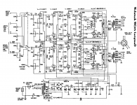
If you look at the schemo, there is a center tapped coil, that goes to the two 12at or z7 tubes.
This coil takes signal from the 12at(z)7 plates, and is in-phase, or "boosting" the drive to the output tubes, through the out transformer.
I verfyied this with Mr scope when I found this problem.
This was done as the 12at(z)7 does not have enough power to drive the 6550s in cathode follower mode.
In these amps the output tubes just sit at idle, and are driven up to power, they have no gain, so the driver has to be pretty good to handle transit response, where short bursts can be ten times higher than the average signal.
My big trick through the years has been to take what I have, and make it work, so I can pay the bills.
This amp came from Italy, the first 275 I re-built or re-paired.
When I had finished re-replacing parts and clean-up, I brought the amp up on the variac and started testing. One channel was distorted, and I found one side of the "coil", or winding to one plate of one 12at(z)7 was open.
So, was there a way to make this amp work without re-winding the output trans, about $350 back then??
What I did, was to un-hook both coils, then I swapped out the 12at(z)7s for 12au7s, as the RCA book shows 330 volts max instead of 300 volts max plate voltage.
What is interesting now that I am looking at this schemo that has 12az7s, is the RCA book shows 330 volts for a 12az7 tube.
I have used 12az7 tubes over the years on guitar amps and some hi-fi and they always had a great sound.
Now what happened in the amp, is that when the winding was out of the circuit, the plate voltage was higher, so I swapped the tubes, and changed the 100k up in value so the plate volts was just a bit lower.
My 275 was not exact the same as the one in the schemo, and voltages might have been higher.
Re-storing a pile of "Macs" over the years, I found, "nothing is certain", as driver assemblies for one model were used in other version amps, color codes not always the same etc...
The driver stage in these amps, is a push-pull, cross - coupled circuit, using both positive and negaive feedback. Macs have a "balancing act" in the driver circuit, and in the out trans also, that provides massive control of the whole audio chain, from in to out.
The smaller amps, like the MC 30, 40 and 60s, and the 225s, are sweeter because the drive voltages/power needed is less to the output tubes, so the sound of the driver stage running high level voltage/power is less.
The 7591 tubes have a lot of gain, and less drive/grid power needs.
The higher power amps, have a "dry" kind of hard midrange sound, as the driver tubes are running very high voltages and working hard.
I also re-stored several McIntosh MIT-200, 200 watt amps with 8005 triodes, and they were truly amazing sound amps.
Hope this explains better
Hi
GridLeak.blogspot.com (I have a lot more to post)
I have been swamped with vintage guitar amps for players, or would have responded earlier.
My brain was "off" when I posted, so here is a better ex-plane-nation
If you look at the schemo, there is a center tapped coil, that goes to the two 12at or z7 tubes.
This coil takes signal from the 12at(z)7 plates, and is in-phase, or "boosting" the drive to the output tubes, through the out transformer.
I verfyied this with Mr scope when I found this problem.
This was done as the 12at(z)7 does not have enough power to drive the 6550s in cathode follower mode.
In these amps the output tubes just sit at idle, and are driven up to power, they have no gain, so the driver has to be pretty good to handle transit response, where short bursts can be ten times higher than the average signal.
My big trick through the years has been to take what I have, and make it work, so I can pay the bills.
This amp came from Italy, the first 275 I re-built or re-paired.
When I had finished re-replacing parts and clean-up, I brought the amp up on the variac and started testing. One channel was distorted, and I found one side of the "coil", or winding to one plate of one 12at(z)7 was open.
So, was there a way to make this amp work without re-winding the output trans, about $350 back then??
What I did, was to un-hook both coils, then I swapped out the 12at(z)7s for 12au7s, as the RCA book shows 330 volts max instead of 300 volts max plate voltage.
What is interesting now that I am looking at this schemo that has 12az7s, is the RCA book shows 330 volts for a 12az7 tube.
I have used 12az7 tubes over the years on guitar amps and some hi-fi and they always had a great sound.
Now what happened in the amp, is that when the winding was out of the circuit, the plate voltage was higher, so I swapped the tubes, and changed the 100k up in value so the plate volts was just a bit lower.
My 275 was not exact the same as the one in the schemo, and voltages might have been higher.
Re-storing a pile of "Macs" over the years, I found, "nothing is certain", as driver assemblies for one model were used in other version amps, color codes not always the same etc...
The driver stage in these amps, is a push-pull, cross - coupled circuit, using both positive and negaive feedback. Macs have a "balancing act" in the driver circuit, and in the out trans also, that provides massive control of the whole audio chain, from in to out.
The smaller amps, like the MC 30, 40 and 60s, and the 225s, are sweeter because the drive voltages/power needed is less to the output tubes, so the sound of the driver stage running high level voltage/power is less.
The 7591 tubes have a lot of gain, and less drive/grid power needs.
The higher power amps, have a "dry" kind of hard midrange sound, as the driver tubes are running very high voltages and working hard.
I also re-stored several McIntosh MIT-200, 200 watt amps with 8005 triodes, and they were truly amazing sound amps.
Hope this explains better
Attachments
What you are calling a booster coil, IOW, is the one of three trifilar windings on the primary of the OPT, that is on the driver. The reason it was changed to this configuration is because of excess voltage on the driver section of previous Unity Coupled amplifiers.
Mc-275 stuff
That could be true, but the winding does add more gain, I tested all with my os-silly-scope, I use all the basic stuff, have no idea what a CAD program is, so I saw proof of this.
Without the winding, the 12at(z)7 stage is just a unity gain kath-ode follower, and I thought right off, when first snooping at a 275 schemo, how odd to add the winding to get more gain, or if reversed, negative feedback to this stage.
The amp sounded soop-er afer the mods, a 12au7 more linear stage.
Using a high-gain tube to drive the grids was to me weird.
The MAc driver stage is all over the place with high-low gain stages
You have to spend a few months inside one to understand one
I mean, what the original reasons, more likely you are right, as Mr Mac was trying to use the 12at(z)7 stages for reasons no one except a few could even guess.
I would love to see the 8005 triodes made again, great sound tube
I think the actual way to make a "Real Mac" is to have a driver transformer, that is coupled to the out trans, maybe all in one, so complete cross-coupled magnetic feedback then
gEo
Last edited:
Psst a heavy octal dual triode such as a 6bl7 will easily drive CF or unity coupled outputs if loaded with a choke. The resonant frequency on the choke is on the order of 2-3 kHz but the heavy triode low plate resistance renders a flat frequency response and very low distortion; so one could build a zero (or very low) global FB circuit which would really update the performance and sound quality.
I had a pair of MI-200s that I switched over to SV-572's. These got rid of the 8005 triode tendency to run away and blow the OPTs when overloaded. Mine were real basket cases so I did a few other mods such as computer grade caps and solid-state rectifiers to replace the overloaded 5U4's; a few driver mods and front end tweaks to stabilize operation, etc. They would literally dim the lights on heavy guitar riffs and were referred to as transcendental sonic projectors as attempt to describe their depth and detail.
- Status
- Not open for further replies.
- Home
- Amplifiers
- Tubes / Valves
- MC275 OPT manual rewinding