Hi,
that T3.1A fuse will pass >700W for an eternity and ~1400W for tens of seconds, maybe even for a few minutes.
Fit a soft start and fuse at somewhere between T800mA and T1.2A
How much does the output offset vary from a cold start up to fully warm? Try using a hair dryer, set to hot, blowing onto the heatsink.
Experiment the other way. Build a safe to use AC coupled amplifier first. Understand how it works. Understand why all those optional extras are really not optional.
Once you are fully informed then make decisions on which components to delete in a forlorn attempt to blow up your speakers.
AndrewT said:Hi,
that T3.1A fuse will pass >700W for an eternity and ~1400W for tens of seconds, maybe even for a few minutes.
Fit a soft start and fuse at somewhere between T800mA and T1.2A
How much does the output offset vary from a cold start up to fully warm? Try using a hair dryer, set to hot, blowing onto the heatsink.
Experiment the other way. Build a safe to use AC coupled amplifier first. Understand how it works. Understand why all those optional extras are really not optional.
Once you are fully informed then make decisions on which components to delete in a forlorn attempt to blow up your speakers.
I've just added a Zobel Network (2R8 & 0.1uf) and changed the location of the FB resistor (R3) so as to reduce the offset
When I apply power the light bulb briefly lights...dims and then relights
I cant see any shorts and this only happens when the amp is connected to the PS
Any ideas?
start measuring voltages to find out what you have on the PCBs.
Otherwise we and you are all guessing.
Otherwise we and you are all guessing.
AndrewT said:start measuring voltages to find out what you have on the PCBs.
Otherwise we and you are all guessing.
The power supply output measures 27v without a load. When I connect the amp, the output drops to just over 9v
Where would you like me to take some readings?
Tripmaster said:
I've just added a Zobel Network (2R8 & 0.1uf) and changed the location of the FB resistor (R3) so as to reduce the offset
Any ideas?
Richard, Richard, Richard..
I take it you added the cap to go with R3?
You will have to remove the Zobel and see if you still have a problem.
No back to front Caps?
Barry.
audio1st said:
Richard, Richard, Richard..
I take it you added the cap to go with R3?
You will have to remove the Zobel and see if you still have a problem.
No back to front Caps?
Barry.
No cap added
oops.
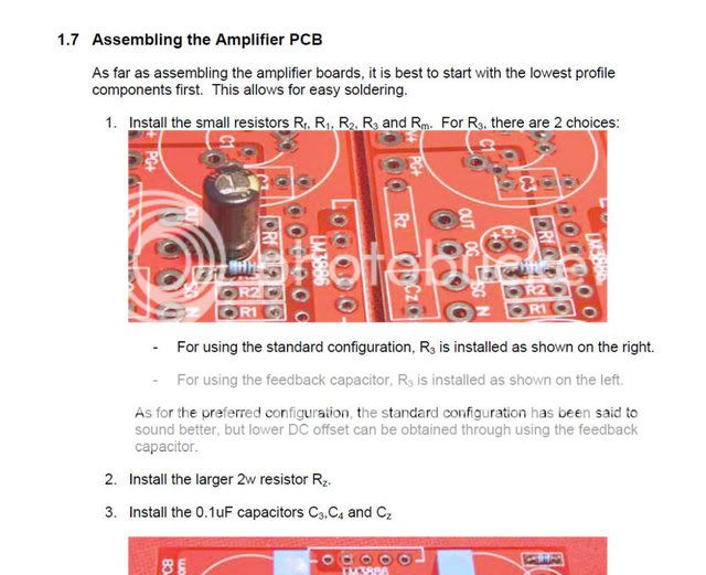
The two pics show the alternatives.
On the left is cap and resistor
On the right is resistor alone.
Doing the left version with no cap leaves the NFB lower leg open circuit.
The minimum gain for the chipamp to remain stable is ~ 10Times (+20dB).
At a gain of one (NFB open circuit) with or without the output Zobel the chipamp is virtually guaranteed to oscillate.
The chipamp may already be damaged.
Build an AC coupled chipamp with ALL the optional add-ons in place and learn how this works.
AndrewT said:oops.
The two pics show the alternatives.
On the left is cap and resistor
On the right is resistor alone.
Doing the left version with no cap leaves the NFB lower leg open circuit.
The minimum gain for the chipamp to remain stable is ~ 10Times (+20dB).
At a gain of one (NFB open circuit) with or without the output Zobel the chipamp is virtually guaranteed to oscillate.
The chipamp may already be damaged.
Build an AC coupled chipamp with ALL the optional add-ons in place and learn how this works.
I have added the cap and now get a 25v output on both sides and a 0.7mV DC offset
AndrewT said:Trip,
can you post a schematic of what you have actually built?
The Chipamp PCB now has 'all' of the components.
http://www.chipamp.com/docs/lm3886-manual.pdf
if you are using the schematic shown then you are still missing the input DC blocking capacitor which also sets the LF roll off frequency and you have no RF attenuation at the input.
The remainder of the output Thiele network is also missing.
Read the National datasheet.
The remainder of the output Thiele network is also missing.
Read the National datasheet.
AndrewT said:if you are using the schematic shown then you are still missing the input DC blocking capacitor which also sets the LF roll off frequency and you have no RF attenuation at the input.
The remainder of the output Thiele network is also missing.
Read the National datasheet.
I have another Chipamp built to the same specs and this sounds and operates OK.
I will Google what you have just mentioned and make the necessary changes.

AndrewT said:Hi,
that T3.1A fuse will pass >700W for an eternity and ~1400W for tens of seconds, maybe even for a few minutes.
Fit a soft start and fuse at somewhere between T800mA and T1.2A
How much does the output offset vary from a cold start up to fully warm? Try using a hair dryer, set to hot, blowing onto the heatsink.
Experiment the other way. Build a safe to use AC coupled amplifier first. Understand how it works. Understand why all those optional extras are really not optional.
Once you are fully informed then make decisions on which components to delete in a forlorn attempt to blow up your speakers.
Hi Andrew
Can I use a NTC thermistor wired in series for inrush limiting?
If so, what resistance/current rating would be necessary for 2x300va transformers?
Thanks
Richard
Puffin said:it's awfully quiet around here:
Oh I'm still here...Too busy listening to the fruits of my labour 🙂
Tripmaster said:
Oh I'm still here...Too busy listening to the fruits of my labour 🙂
Oh well you're obviously too busy to let us know what it sounds like, unless of course it sounds rubbish 🙄
Tripmaster said:
Hi Andrew
Can I use a NTC thermistor wired in series for inrush limiting?
If so, what resistance/current rating would be necessary for 2x300va transformers?
Thanks
Richard
Hi
Sorry to bother you…but I have started to put together a parts order and wondered if one of these would be ok?
Thanks for your help
Richard
Hi,
the CL60 is recommended by many that use 110/120Vac.
I like 50r to 100r of power resistors on 240Vac.
the CL60 is recommended by many that use 110/120Vac.
I like 50r to 100r of power resistors on 240Vac.
AndrewT said:Hi,
the CL60 is recommended by many that use 110/120Vac.
I like 50r to 100r of power resistors on 240Vac.
Thanks Andrew
I will have a look at these
Richard
- Status
- Not open for further replies.
- Home
- Amplifiers
- Chip Amps
- May I have some help regarding..Electrical safety,Star Grounding and Suggested Layout