Tiredness got the better of me tonight!
Earlier this evening I connected the the umbilicals and applied power. With everything measuring as it should I decided to connect the Chipamp PCBs to the power supply. This time the light bulb tester lit up and for some crazy reason I decided push the bypass switch!!! This resulted in a loud crack.
I then noticed I had connected both V+ and PG+ to the power supply V+
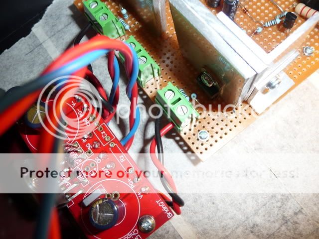
The green terminal block in the middle is Ground
I have just measured the V+ output from the power supply and I don't get and reading, but I do get a reading of 27v across the Zener and 35.4v from various points on the strip board if I connect the DMM probe to another ground location.
The V- output is 35.4v from the green terminal block
Where would you recommend I start fault finding (tomorrow that is!)?
What an idiot!!!
Earlier this evening I connected the the umbilicals and applied power. With everything measuring as it should I decided to connect the Chipamp PCBs to the power supply. This time the light bulb tester lit up and for some crazy reason I decided push the bypass switch!!! This resulted in a loud crack.
I then noticed I had connected both V+ and PG+ to the power supply V+
The green terminal block in the middle is Ground
I have just measured the V+ output from the power supply and I don't get and reading, but I do get a reading of 27v across the Zener and 35.4v from various points on the strip board if I connect the DMM probe to another ground location.
The V- output is 35.4v from the green terminal block
Where would you recommend I start fault finding (tomorrow that is!)?
What an idiot!!!
Puffin said:What a bummer. Hope you get it sorted.
I have quite a few spare parts for the ps so it shouldn't take too long to get it up and running

audio1st said:Hi Richard,
You may have just blown the copper track somewhere?
So check them first..
Barry..
I really shouldn't try to finish this project when I am tired.
I'll check now
Tripmaster said:
I really shouldn't try to finish this project when I am tired.
I'll check now
Yep, just after the 47uf cap where the track width was thinner due drilling a hole for a component.
I'll repair and report back.
OK I am getting 34.8v from the output.
Is there likely to be a component to fail first with this wiring error?
I guess it might be a good idea to check the working PS at various points and compare with the faulty board.
Is there likely to be a component to fail first with this wiring error?
I guess it might be a good idea to check the working PS at various points and compare with the faulty board.
Tripmaster said:OK I am getting 34.8v from the output.
Is there likely to be a component to fail first with this wiring error?
I guess it might be a good idea to check the working PS at various points and compare with the faulty board.
The BD 911, would be my first choice..
audio1st said:
The BD 911, would be my first choice..
I have just compared all of the Darlingtons with a working PS and the first BD139 is reading 34.7v from the emitter when it should be reading 27v.
I guess its worth starting with this one 😉
Hi Richard,
If the reg board input is the same as the output, then there is no volt-drop across the BD911.
If a preceding transistor is faulty, there should still be a volt-drop across BD911, (approx. 1.7V).
Two other concerns, you may need to beef up your tracks and what fuse are you using at the mains input?
Barry.
audio1st said:Hi Richard,
If the reg board input is the same as the output, then there is no volt-drop across the BD911.
If a preceding transistor is faulty, there should still be a volt-drop across BD911, (approx. 1.7V).
Two other concerns, you may need to beef up your tracks and what fuse are you using at the mains input?
Barry.

You were absolutely right....Thanks!
I changed the BD139 and it didn't make any difference, as soon I changed the BD912 and BD911 the output returned to 27v
Talking of Stars...do I connect the Chipamp PG- and PG+ to the correct ground points on the Reg PS and then run the solid copper wires from the Reg PS ground output to the star ground point?
Richard 🙂
Tripmaster said:
Talking of Stars...do I connect the Chipamp PG- and PG+ to the correct ground points on the Reg PS and then run the solid copper wires from the Reg PS ground output to the star ground point?
Richard 🙂
Hi Richard,
PG- and PG+ connect to the correct grounds on the Regs board.
PG- and PG+ are joined on the amp board so this is the the star point.
CNG connects to the chassis ground but may need a network to avoid hum...
Barry.
audio1st said:
Hi Richard,
PG- and PG+ connect to the correct grounds on the Regs board.
PG- and PG+ are joined on the amp board so this is the the star point.
CNG connects to the chassis ground but may need a network to avoid hum...
Barry.
Thanks...I'll get to work

I've just connected one channel and I am getting 70mV DC offset without a connected load, so the chip is probably OK.
Thanks Barry
Thanks Barry
Tripmaster said:
I really shouldn't try to finish this project when I am tired.
I'll check now
Attachments

70mV is very high.Tripmaster said:I've just connected one channel and I am getting 70mV DC offset without a connected load, so the chip is probably OK.
Thanks Barry
What is the voltage across the Zin resistor?
Puffin said:
LOL...paternity leave...a good time to bond with ones soldering iron😀
AndrewT said:70mV is very high.
What is the voltage across the Zin resistor?
The board doesn't have a Zobel at the moment and feedback resistor is soldered to the 'Standard position' as per the Chipamp instruction manual, there is also no feedback capacitor.
I thought I would add the components in stages as some have reported slightly better sound without.
70mV is high but I think I am right in thinking its not enough to damage the speakers.
Would you use a Zobel, and if so can you match the resistor value to the connected speakers?
- Status
- Not open for further replies.
- Home
- Amplifiers
- Chip Amps
- May I have some help regarding..Electrical safety,Star Grounding and Suggested Layout