AndrewT said:Hi,
the CL60 is recommended by many that use 110/120Vac.
I like 50r to 100r of power resistors on 240Vac.
Hi Andrew
The CL60 is rated at 10R. Is 10ohms on a 240vac supply to low?
Does it need to be 50r - 100r?
Thanks
Richard
Hi,
the 10r cold resistance will reduce the peak start up current.
This will allow a lower value fuse to be used.
Try a series pair of CL60 for 220/240Vac use, or CL60+20r.
These options will reduce the peak current even further.
CL60 are expensive.
the 10r cold resistance will reduce the peak start up current.
This will allow a lower value fuse to be used.
Try a series pair of CL60 for 220/240Vac use, or CL60+20r.
These options will reduce the peak current even further.
CL60 are expensive.
Are we the only folk capable of telling the truth?Nuuk said:
Only a Scot would say that! 😀 😀 😀
Two CL60s come to about £4. Five 10r 5W WW radials (that I have 1000off) are just £1 for the set.
That's a much better price.
I see from the datasheet that cl70 or cl80 may better suit UK voltage.
I see from the datasheet that cl70 or cl80 may better suit UK voltage.
Are you taking notes Richard? Not only are we helping you to build a PSU but helping you beat the credit crunch too! 😱
Phew...its a good job I took a punt last night, as these came today!
£1.48+VAT......can you put a price on Safe.T? 😉
Is there a recommend way of attaching these bearing in mind the heat they produce?
Richard
£1.48+VAT......can you put a price on Safe.T? 😉
Is there a recommend way of attaching these bearing in mind the heat they produce?
Richard
Hi
Would it be OK to mount thermistors like this?
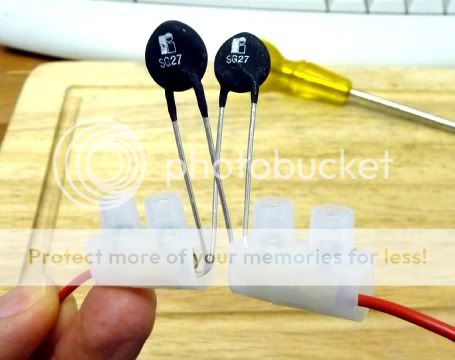
Just after the mains switch in line with 'Live' wire.
I intend trim the legs and securely mount the terminal block to the chassis.
Thanks
Richard
Would it be OK to mount thermistors like this?
Just after the mains switch in line with 'Live' wire.
I intend trim the legs and securely mount the terminal block to the chassis.
Thanks
Richard
Hi,
if you keep the two terminals side by side (not split), you can insert the Thermistor without bending any legs.
Insulate the chassis under the terminals and thermistor.
Double insulate the live and neutral wires inside the chassis.
All these components are at Live potential. Protect them from wayward fingers and dropped tools.
I am not at all sure that parallel NTC thermistors will work.
The one that has slightly lower resistance will pass more current. This will heat it and drop the resistance even more, passing a bigger proportion of the total current draw. Then around that circle again. Effectively one device is doing all the work and dissipating most of the heat and thus setting your thermistor current limit.
Your pic shows quite small Power Thermistors. One of these may not suit soft starting a transformer.
You could series connect the two Thermistors using a 3way terminal strip with Live in and out through the outer terminals.
- Status
- Not open for further replies.
- Home
- Amplifiers
- Chip Amps
- May I have some help regarding..Electrical safety,Star Grounding and Suggested Layout