Gino,
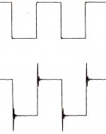
Boucherot cell and damped inductor are 2 counteractive measures for
inductive and capacitive loads( speakers) or internal capacitance of speaker
cabling. These simple networks can prevent overload of an amplifier output
stage. A typical value of output inductor is in the range of 1-2 uH(micro).
If you wanted to simulate a very bad reactive load and see what would a high
frequency square wave signal look like with and without said measures, here
it is. The one without spikes is OK.
Attachments
Last edited:
Lojzek. Very good info. A bad analogy might be the capacitor found on old contact points to the HT coil of a car. With the usual capacitor all is OK. With the wrong one or none/broken all is not OK. When correct the spark at the points seems small and the spark plug large. So simple and then again not simple.
My friend built an amplifier to use with Helmholtz coils to measure and calbrate magnetometers. Although not very high current the coils stored plenty of energy. This seemed to defeat any calculation as to SOA. The main problem was voltage doubling.
Your graph tells me two things. Going active will not cure everything. Secondly, keeping it simple will sound better. I have thought for some time semi active the best route. That is one pole passive and all others active. Food for thought.
My Magneplanars ( SMGa ) are nice. They claim a resitive load of 4R. The listening window is small as the only demerit. Much like a Quad ESL but easier to live with. Not very fussy as a Rotel RA931 proved recently. I also own some Dynaco A25's. Had some in 1974 so bought some recently. Gradually falling in love with them again. I hope to do a class A tweeter mod for the A25's. Simple op amp with booster transistors. The op amp can be a filter also. A25 has no bass unit filter, that helps.
A25 has no bass unit filter, that helps.
Except for that one built into the voice coil. Inductance =3.8 mh.
You are dealing with a foot of wire. What was the inductance of the stock wire? What is the inductance of your replacement? What does the difference buy you? Is there an inductor on the output of the power amps?
He claimed that with this tweak the speaker now had "clarity and dynamics to die for". I never realized that such a small change in inductance could have such a large effect.
I'll stop kidding you now .... maybe
He claimed that with this tweak the speaker now had "clarity and dynamics to die for". I never realized that such a small change in inductance could have such a large effect.
I'll stop kidding you now .... maybe
I was a bit perplexed when I read about the modifications too. Obviously the speakers must have had all that clarity and dynamics to start with and they were hidden until the person thought they had uncovered them. No way those changes would have done much to change the sound. With changes like that I thought the crossover was going to have been redesigned.
Gino,
Boucherot cell and damped inductor are 2 counteractive measures for
inductive and capacitive loads( speakers) or internal capacitance of speaker
cabling. These simple networks can prevent overload of an amplifier output
stage.
A typical value of output inductor is in the range of 1-2 uH(micro).
If you wanted to simulate a very bad reactive load and see what would a high frequency square wave signal look like with and without said measures, here it is. The one without spikes is OK.
Hi and thanks but this is difficult for me
Some measurements, like the one you very well propose, are very useful because it is easier to see than to listen.
I am a little intrigued by the response to square waves also for drivers, even if the SW does not exist in reality.
I would like to see the square wave response of a woofer at let's say 100-200 Hz and then the response of the same woofer at the same freqs but with an inductor in between.
If they are practically identical this means to me that the inductor is perfectly transparent.
I really wonder if this will happen ... i would be very curious to see.
But if you tell me so i will trust you completely.
All this mumbling of mine has been generated by reading a review on an inductor less Epos speaker.
The designer tried hard to avoid using an inductor in series with the woofer i guess for some technical reason, but could it be only a marketing decision ?
Thanks a lot again, gino
Last edited:
Except for that one built into the voice coil. Inductance =3.8 mh.
Did anyone make a Zobel for Dynaco A25 bass unit? I now realise I have to try. What a golden chance. Thanks for saying as being humble designs my perfectionist nature button was turned off. I had this with motorcycles. When working as best they can they are not the same animal humble or not ( e.g.bearings in swinging arm or fork sliders, then the obvious stufff ). In cars this is the suspension brace. So simple, so logical.
Hi,
I find this thread more lively than before... not only a shopping list anymore !
At Max, May you test & try something for my understanding please : If you double (or more: x 3... x4!) only the Gnd (minus return path wire) section of the wires in the speaker and the same for the Gnd (minus return path wire) between the speaker and the amp: what do you hear ? Something more soft and heavy or no changes ?
I surmise low efficienty driver to be sensible to such mods. Call it myself magic as I don't understand what is involved here (just less resistivity of the return path wire ?).
cheers
Hi Eldham.Hi, Max, May you test & try something for my understanding please : If you double (or more: x 3... x4!) only the Gnd (minus return path wire) section of the wires in the speaker and the same for the Gnd (minus return path wire) between the speaker and the amp: what do you hear ? Something more soft and heavy or no changes ?
I surmise low efficiency driver to be sensible to such mods. Call it myself magic as I don't understand what is involved here (just less resistivity of the return path wire ?).
cheers
In this experiment i have used four strands of enamelled wire between the amplifier module each channel output pins and each speaker driver connections...two for active, two for neutral (earth) per channel...two custom cables, 8 wires total.
Nothing fancy, no elaborate braiding etc, just four wires x 0.8mm x 350mm per channel.
Dan.
All this mumbling of mine has been generated by reading
a review on an inductor less Epos speaker. The designer
tried hard to avoid using an inductor in series with the woofer
i guess for some technical reason, but could it be only a marketing
decision ?
I would love to read that review just for fun, if you can share the link.
An inductor is a very simple passive part. Its primary function is to attenuate AC
frequencies. Some more, some less, depending on the inductance value. Why
would any manufacturer want to avoid using one for XO filter, I can only guess.
Maybe to offer something others don't or trying to evade XO filter expense.
Speakers not having inductors would measure a FR with prominent midrange
frequencies (baffle step) and higher frequencies common to the properties
of the cone material used. All you need to know about it is shown on the graph.
A real driver in a box without any filtering and with a 2,0 mH( dcr 0,5) LP.
This is only a half way done filter. It lacks a capacitor.
What counts for having a transparent sounding device is smart overall design
with regard to the rules of good engineering. Passive parts are never an issue
when used reasonably. Manufacturers know that way better than us.
Attachments

Oups... Just understand that the amplifier is close as it is in the speaker... so maybe just adding a greater section just for the minus section between the embeded and driver could change nothing (because too short length!)
By the way could be interresting for you trying : just double the section of the wires just for the minus as you already heard a great difference with changing the + and - wires already ! Simple and informative...
With my low effcienty speaker (Boston Lynnfield 400L : 85DB/2.83 V) and 3 meters of cable i can hear a difference of sound when I just increase the section of the Minus wires between speaker and amp by only 1/3 ! It adds a "thicker" sound ! Don't understand how this electrical damping works as the amp is a strong one (CHORD spm 1000B : 2 x 250 W at 4 ohms !)
cheers,
PS ! Interresting input than yours : some cheap speakers can also sound great if correctly modded and the icing of the cake is you gave us this mods ! 🙂.
Dan,I am running a pair of these Behringer Truth B2031A active monitors.
Now modified, these are one of the best loudspeakers I have heard.
As standard they were sending me out of the room, now they are pin sharp in clarity/detail, centre, width and depth imaging.
These loudspeakers are both clinically detailed and perfectly musical, and go pretty loud.
These are seriously good fun, and at their price point quite unbeatable.
Dan.
View attachment 446478
View attachment 446479
View attachment 446481
View attachment 446482
in the pictures, is that the original damping material?
Could you provide pictures of your modifications, please?
Thanks in advance,
Edwin
I would love to read that review just for fun, if you can share the link.
An inductor is a very simple passive part. Its primary function is to attenuate AC frequencies. Some more, some less, depending on the inductance value. Why would any manufacturer want to avoid using one for XO filter, I can only guess.
Maybe to offer something others don't or trying to evade XO filter expense.
Speakers not having inductors would measure a FR with prominent midrange
frequencies (baffle step) and higher frequencies common to the properties
of the cone material used. All you need to know about it is shown on the graph.
A real driver in a box without any filtering and with a 2,0 mH( dcr 0,5) LP.
This is only a half way done filter. It lacks a capacitor.
What counts for having a transparent sounding device is smart overall design
with regard to the rules of good engineering. Passive parts are never an issue when used reasonably. Manufacturers know that way better than us.
Hi an thanks for the valuable explanation.
This is the pdf of the speaker with some description of the inductor less phylosophy
http://www.eposltd.com/archive/epos-es11.pdf
but still the square wave response could tell something that the freq response does not tell.
It is a very extreme test from what i understand.
How inductors pass a square wave ?
An externally hosted image should be here but it was not working when we last tested it.
Thanks again, gino
Gino,
you posted an LR circuit and once you start this circuit with
an input signal like square wave of unknown frequency,
resistor and inductor value, by placing oscilloscope probes on
either of passive parts, you get the pictured plots. Depending
on time constant of this circuit, which can be anything, since
nothing is defined, the curves could be anything.
Inductor graph tells us that the time constant of it must be
pretty short since the inductor managed to store the energy
before the change of duty cycle and the voltage dropped to
zero line until the negative signal came along and the process
went the other way.
This doesn't tell anything negative about inductors in passive filters.
Hi Edwin.Dan, in the pictures, is that the original damping material?
Could you provide pictures of your modifications, please?
Thanks in advance,
Edwin
The grey damping material is original....those four photos are off the net.
Yes, during the next few days I will dismantle the modified boxes and take photos.
I will also swap in the original condition pair of 2031A that I have, take a listen and describe the sonic/subjective differences.
Dan.
Thanks Dan!
I was contemplating to modify my own 2030A's. Already did the power supply.. added some electrolytics and PP... Unfortunately space is very limited... too limited for adding large amounts of uF. This limited mod improved the sound. A bit more punch and a little more detail in the highs...
Unfortunately the bass-speakers produce a bit dull/coloured sound. Your modifications might be able to fix that ..
Cheers.
Edwin
Today, I found some courage to loosen the screws and take a look inside the 2030A's.
Indeed... about the same as in the 2031A's : minimal damping material. So I took a peace ( 11cm x 22cm) of foam that was laying around, curled it up and stuffed it behind the tweeters...
Boxiness disappeared instantly and a lot more definition 😎

Indeed... about the same as in the 2031A's : minimal damping material. So I took a peace ( 11cm x 22cm) of foam that was laying around, curled it up and stuffed it behind the tweeters...
Boxiness disappeared instantly and a lot more definition 😎
An externally hosted image should be here but it was not working when we last tested it.
The change in damping may be as simple as overdamping (or correctly damping) the vent tuning.
I don't think I'd attribute anything to the inductance of the wire, which is dramatically swamped by voicecoil inductance, it may have different mechanical resonant characteristics.
I don't think I'd attribute anything to the inductance of the wire, which is dramatically swamped by voicecoil inductance, it may have different mechanical resonant characteristics.
Last edited:
... Trying the spoken/ummm/oooooh/ahhhh testing sounds into the original cabinets excited all sorts of booming and emphasis.
Doing the same into the relined versions, I could not excite any resonances...just well behaved, with really good damping.
The result now is a pair of speakers that have clarity and dynamics to die for.
.... Dan.
Hi Dan !
interesting test but i am not sure to have understood completely 😕
Could you tell me some more ? Is it difficult to perform ?
Regarding the cabinet, as i said, i am impressed by the construction also of the stock version. The internal bracing looks particularly well executed.
I will try the new and very interesting damping material not only with this speaker. 😉
Thanks a lot again, gino 🙂
- Status
- Not open for further replies.
- Home
- Loudspeakers
- Multi-Way
- Max's Behringers