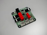
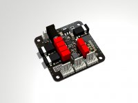
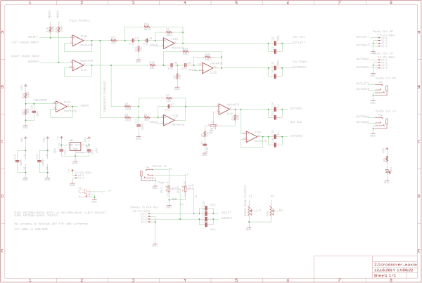
Suitable crossover for the MAX9709 boards. (Same shape)
Linkwitz-Riley configuration, x-over at 200Hz, single ended configuration.
Input:
3.5mm jack pre-potentiometer
3.5mm jack bypassed potentiometer
4x pinheader post-potentiometer
Output:
3.5mm jack Highpass Stereo
3.5mm jack Lowpass Mono+Mono with adjustable gain
4x pinheader Highpass Stereo
4x pinheader Lowpass Mono+Mono with adjustable gain
Coupling caps are either MKS2 (Wima) or 1206 X7R ceramics.
aktive 2.1 Crossover/Frequenzweiche mit MAX4478 - #360customs
What opamp are you using?
MAX4478, should be sufficient for this purpose.
MAX4478 SOT23, Low-Noise, Low-Distortion, Wide-Band, Rail-to-Rail Op Amps - Maxim
Low Input Voltage-Noise Density: 4.5nV/Squareroot
Low Input Current-Noise Density: 0.5fA/Squareroot
Low Distortion: 0.0002% THD+N (1kΩ load)
Single-Supply Operation from +2.7V to +5.5V
Input Common-Mode Voltage Range Includes Ground
Rail-to-Rail Output Swings with a 1kΩ Load
10MHz GBW Product, Unity-Gain Stable (MAX4475-MAX4478)
42MHz GBW Product, Stable with AV > +5V/V (MAX4488/MAX4489)
Excellent DC Characteristics
VOS = 70µV
IBIAS = 1pA
Large-Signal Voltage Gain = 120dB
Attachments
Ceramics are okay when voltage rating is much higher than signal amplitude.
App-Note:
http://pdfserv.maximintegrated.com/en/an/AN4333.pdf
We also did a measure of ceramics as coupling caps on the MAX9709. There were nearly small to none influence.
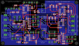
Yours pcbs signal ground loops are rather big, i would do some via stitching and rearrange the components a bit.
http://www.eetimes.com/document.asp?doc_id=1272321
http://www.hottconsultants.com/techtips/tips-slots.html
http://www.hottconsultants.com/techtips/split-gnd-plane.html
http://www.hottconsultants.com/pdf_files/june2001pcd_mixedsignal.pdf
http://www.hottconsultants.com/techtips/red_flags.html
App-Note:
http://pdfserv.maximintegrated.com/en/an/AN4333.pdf
We also did a measure of ceramics as coupling caps on the MAX9709. There were nearly small to none influence.
Yours pcbs signal ground loops are rather big, i would do some via stitching and rearrange the components a bit.
http://www.eetimes.com/document.asp?doc_id=1272321
http://www.hottconsultants.com/techtips/tips-slots.html
http://www.hottconsultants.com/techtips/split-gnd-plane.html
http://www.hottconsultants.com/pdf_files/june2001pcd_mixedsignal.pdf
http://www.hottconsultants.com/techtips/red_flags.html
Last edited:
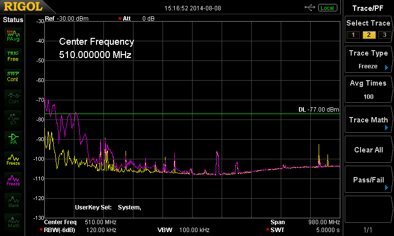
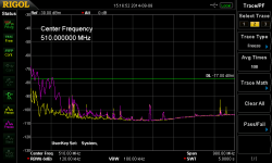
Regarding RF+HF within a filterless design, our/my MAX9709 performs like shown.
Test setup:
40cm cable on one channel with a 10Ohm load
wideband-antenna (EN61000-6) (30MHz - 1GHz) RMS/AVG
measured 3 meters away
yellow: background (radio-stations etc.)
magenta: background + MAX9709 pcb
-77dBm is ~ the EMI limit
Test setup:
40cm cable on one channel with a 10Ohm load
wideband-antenna (EN61000-6) (30MHz - 1GHz) RMS/AVG
measured 3 meters away
yellow: background (radio-stations etc.)
magenta: background + MAX9709 pcb
-77dBm is ~ the EMI limit
Attachments
Those are beautiful PCBs doctormord.
How does the MAX9709 compare to the TI TPA311x chips? I guess a close match power-wise would be the TPA3118.
How does the MAX9709 compare to the TI TPA311x chips? I guess a close match power-wise would be the TPA3118.
Never treid/heard/tested the TPA-chips, so i can't compare.
(Beside that the TPA-ICs are twice in size and not that power-efficient at low volume.)
(Beside that the TPA-ICs are twice in size and not that power-efficient at low volume.)
hai sir i working this MAX9709 at 20V and 4 ohm load but it is getting very much heat do u have any suggestion for this problemCheers,
i build myself a 9709 monostage in 1-layer-design. So far temperature is not a problem, but i havent tried a 100%-run on 22V.
Powered by 12V PSU the IC topside will be at ~42°C after 10 minutes of 1kHz square wave input near clipping, so at 12V supply voltage, no additional heatsinking is required.
Strangely the IC is only pulling some 800mA from the PSU at this, so i gues impedance of the speaker is not as low as 4ohms.
Layout is working as is and it is considered to place a heatsink on the bottom side of the pcb.
Working params are:
SSM 200kHz +/-4
Mono bridged (1x50W)
22V max input
36dB gain
120°C temp shutdown via /mute input
filterless output
Cheers doc
Hello
i am working on MAX9709 amplifier i am operating at 20V and 4 ohm load but ic is getting very much heat .....??????????????
i am working on MAX9709 amplifier i am operating at 20V and 4 ohm load but ic is getting very much heat .....??????????????
What is your system idle current?
Do you have sufficient cooling via GND-plane and the bottom thermal-pad?
Do you have sufficient cooling via GND-plane and the bottom thermal-pad?
Btw:
I actually got some ready build spare boards fs:
http://www.diyaudio.com/forums/vend...ased-class-d-amplifier-board.html#post4153396
I actually got some ready build spare boards fs:
http://www.diyaudio.com/forums/vend...ased-class-d-amplifier-board.html#post4153396
Is it ok if use ceramic cap in signal path?
I did my crossover with MKS2(wima) cap. Its 3 way.
Have you got a schematic for this please.
If someone wants to see what a simple ferrite-bead+c filter does to EMV/EMI, i did some measurements here (with comparsion to the TPA3132D2):
TPA3132D2 vs. MAX9709 Messungen EMI/EMV - #360customs
The MAX9709 can really be run fully filterless, thanks to a "special modulation sheme + SSM".
TPA3132D2 vs. MAX9709 Messungen EMI/EMV - #360customs
The MAX9709 can really be run fully filterless, thanks to a "special modulation sheme + SSM".
I hope it doesn't bother you reviving this old thread. At the moment i'am looking into active crossover designs using linkwitz-riley 12db slopes. I found your crossover board on this thread and 360suctoms site, but could not find more info. I want to use it in a small bluetooth speaker to practice some elecktonics and the single rail seems handy.
Now using elliot sound calculator i came across a different layout compared to yours, am I missing something?

for the high pass you changed the position of the resistor to ground and resistor over the opamp. What is the impact of this change?
last thing is; how do you mute the output in your design when powering down?
Now using elliot sound calculator i came across a different layout compared to yours, am I missing something?
for the high pass you changed the position of the resistor to ground and resistor over the opamp. What is the impact of this change?
last thing is; how do you mute the output in your design when powering down?
- Home
- Amplifiers
- Class D
- max9709