jzagaja said:What do you think about topcoat instead of a paint? After grinding and polishing it looks like this one:
http://www.zgpph.com/kolumny/zdjecia/mietki_03.jpg
That finish is most likely not clear coated if thats what you mean by "topcoat". It looks to be a classic black polyurethane buffed to a high finish. But its still "paint".
sometimes they refer to certain powder coatings as topcoatings. I don't know enough about them to understand why some are called topcoatings and some are called base coatings. They are colored, not clear, so it's not just a top clear coat, it's something else.
Well I contacted the Chris from Timber Nation about maybe making me a custom stand. I just can't find what I want. I'm thinking that these speakers really have the proportion of classic 60's-70's speakers, and are still reminiscent of the BBC designs from companies like Harbeth. Taking cues from the stands commonly used with their larger designs, I'm thinking that something of similar or identical dimensions to the bass would be best. I'm hoping that Chris will be willing to make me such a thing, we shall see. I'd like to spend as little as possible on these stands. Ideally that would be less than 300, but I would stretch it to 500 if they were really nice. Say something in solid walnut with a nice design and finish.
I have this idea for a stand that uses these blocks of wood which are each 2-3" thick, separated by a 1/2" to 3/4" piece which is much smaller, giving the illusion that the blocks are floating on top of each other. Having these stacked on top of each other for a total height with spikes of say 14"-16". It's a very modern style, and I've seen coffee and end tables sort of like this. We shall see if such a thing is possible. I haven't been able to find an example on the web, and I'm not so good with computer renderings.
Matt
I've made stands before, its not too hard. I'll send you pictures or drawings of mine. At the prices you seem to be willing to pay, I might be interested in doing them.
I've made stands before, its not too hard. I'll send you pictures or drawings of mine. At the prices you seem to be willing to pay, I might be interested in doing them.
R-Carpenter said:Sploo, it's a specific compressor with a set of filters. I don't remember which one I've used but it was always a nice clean flow of cold air. The system (mask, compressor and accessories) coasted $900.
It was about 15 years ago.
May be there's a set of filters that can create breathable air from regular compressed air, that I am not sure.
Air fed is very awkward to works with and you also have to consider where to locate the feeding compressor itself. Did you end up making yourself a small spray booth?
Roman.
Hi Roman,
I found a couple of forum discussions on the subject of air-fed gear. The gist seems to be that you can use an oil based compressor, with a water trap (got one) but you then need a block of three ever finer filters to get the air quality up to Class D.
When you look at an air-fed mask, they're actually really simple - just a hood with a loose cloth that fits round your chin, and the air blows into the volume to positively pressurise it with good air. Given the gentle blow that comes out, you could easily provide a much more simple air line (it seems to me it's just the thin tubing that requires the initial high pressure from a compressor).
I had wondered about making a simple pump that would blow high CFM, low pressure, air through a wider diameter tube, and adapt that to blow inside the mask. I'd use an array of axial fans for computer CPU use - cheap, and I'd hope wouldn't result in much in the way of particulates in the air (the intake would be anywhere well away from the painting).
As for a spray booth, I have a large and well ventilated area - it's called my garden. Hence it's not really suitable due to the weather (for most days) but I'd be really reluctant to spray indoors without air-fed gear.
pjpoes said:...I have this idea for a stand...
Matt,
Perhaps you could build a stand similar to the center unit I made? The pics I've linked don't show it that well I'm afraid (can't find a better one right now). Basically it's two pieces of plastic pipe (rectangular cross section, with rounded edges) that I recessed into two sheets of MDF. The pipes were filled with sand, and the whole lot sprayed white.
A taller version (without the angle) would probably compliment the speakers quite well.
http://spikyfish.com/speakers.jpg
http://spikyfish.com/longball/IMG_2226.jpg
Hi Sploo, thanks, that's not really what I'm looking for. Those are easy enough to make, but I'm looking for a different style.
Dr. Geddes, did you get my email concerning measurements. I no longer think the first one is accurate, as I can't repeat it. However the second one does seem to be (though I know it needs to be taken as a spatially averaged response.
I will redo the initial near field measurements, again at 2 meters, and send you those if you want. Again though, I would appreciate any recommendations on the best way to take measurements to trouble shoot any potential issues.
I will redo the initial near field measurements, again at 2 meters, and send you those if you want. Again though, I would appreciate any recommendations on the best way to take measurements to trouble shoot any potential issues.
Matt, you won't be able to measure the free field response at 2m distance in a normal room. There are just too many reflections.
Best, Markus
Best, Markus
Ok I took some measurements I'm a bit more comfortable with. Ok, first, these are not free field spatially averaged measurements of the speakers. Those will come, but I need to wait. True free field needs to wait until it's warmer outside, but I can't even move these to the center of the room until I get some help moving things around. In the mean time, these are measurements I took on the listening axis (not on-axis) at 2 meters. I didn't splice in the response below 350hz on this one, so don't trust anything below 3-400hz.
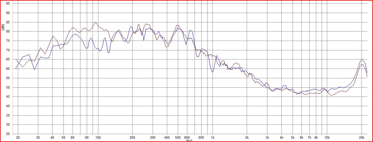
Overall it looks good to me, but there are a few things I'm wondering about. Hopefully Dr. Geddes can comment on them. First thing is the small trough in the crossover area. At first I thought I had hooked the tweeters up backwards, so I tried reversing them and remeasuring, but it made the trough a little deeper, so that doesn't seem to be the issue. There are incorrect value resistors in one of the LCR's, so that might be the reason. The measurements are the Left and Right speakers over-laid on each other. I was curious how similar they were. It's really not a good measure as the speakers are in their listening locations, not free field, so what it shows is the combination of any speaker differences combined with the larger room effects differences. Additionally, it was taken at 2 meters, not the 4 meter listening distance, so there is even more room effects at that distance.

Overall it looks good to me, but there are a few things I'm wondering about. Hopefully Dr. Geddes can comment on them. First thing is the small trough in the crossover area. At first I thought I had hooked the tweeters up backwards, so I tried reversing them and remeasuring, but it made the trough a little deeper, so that doesn't seem to be the issue. There are incorrect value resistors in one of the LCR's, so that might be the reason. The measurements are the Left and Right speakers over-laid on each other. I was curious how similar they were. It's really not a good measure as the speakers are in their listening locations, not free field, so what it shows is the combination of any speaker differences combined with the larger room effects differences. Additionally, it was taken at 2 meters, not the 4 meter listening distance, so there is even more room effects at that distance.

these are cabinet panel vibration measurements taken with an accelerometer. Without a proper point of reference this won't mean much to you, but having used it a bit myself, I know what different boxes look like. This is pretty typical of a decent box. I will try to put up measurements of my subwoofer box too for comparison, that box uses 1.5" thick mdf with extensive bracing throughout, as well as a lot of dampening. In this picture you see two lines, the red one is the box built as Dr. Geddes suggests. The Blue line is with Parts Express Sonic Barrier 1.5" foam with the dampening layer. As you can see this significantly reduced energy in the 150hz on down range. It had no effect in the area it would probably be most audible, so I would argue it's unnecessary. Probably reducing energy in that area is going to require either more bracing and/or further constrained layer. The audible effect is probably minimal, so I probably won't play around with the cabinet dampening any more, it's really pretty good.

this graph has the dampened speaker box in blue and the sub box in red. Again, the sub box was uber over kill, and there is really only a small difference in the midrange area. The bass area is tough as the sub has considerably more energy than the abbey's below 100hz, so you see that reflected in the graph.
Under 300Hz may not be trustworthy of what they will do in other rooms, but very tell tale of what they do in your room, for that mic position. Nice room curve tilt and very even bass with the subs. Dr. Geddes will tell you if the crossover trough is normal, but I would not expect much power response from a large diameter woofer up there in general. You get long averaged total energy in one arbitrary position with an open window the way you measured, so it may well be valid, if there isn't a problem with parts. Congratulations for your efforts so far.
yeah, I know my measurements are very specific to my room. Most of the recently posted ones are spatially averaged now, but the speakers are not sitting in a big open space, they are 14" from the wall where they sit for normal listening. Basically, this shows what the speakers perform like in my room. The crossover trough seems to be a part of the speaker as it's showing up in every measurement I take, regardless of position, and doesn't seem to change much.
That bass response is with only 2 subwoofers. I think a third one designed around 50-150hz will help things further, as well as playing around with the crossover points of each individual sub and the eq some more.
That bass response is with only 2 subwoofers. I think a third one designed around 50-150hz will help things further, as well as playing around with the crossover points of each individual sub and the eq some more.
Off course you probably can do better for bass in the end, but for what it is, does great versus the two room symmetrical LF sources of the average stereo installation. Their peaks and cancellations can be scary... You have 4 LF sources scattered in total for now, not only the subs, the mains are LF sources too. A way better approach for the modal region, as Dr. Geddes has explained many times before. More subs will be better. I don't know if your center channel can be counted in later too, given the way they mix video sound in surround productions today, something which I don't know much about.
modern surround is mixed with a center image that is every bit as full range as the L-R channels. I would think the center is every bit as much a low frequency source too.
pjpoes said:
There are incorrect value resistors in one of the LCR's, so that might be the reason. The measurements are the Left and Right speakers over-laid on each other.
What component value is different and what is the difference?
Are these spatially and frequency averaged at all?
the LCR that was supposed to have a 2.7ohm resistor (The one I was missing and am still waiting on) was replaced with a 4 or 6 ohm resistor. I meant to use 4 ohm's, but noticed I had a 4 ohm, so it's possible one has a 6 ohm in it.
At the listening position there is a spatial averaging used as per the ATB recommendation at the listening position. It's not over a large area though. The test tone used is the ATB continued measure + "for anechoic measurements in room." I'm not arguing my measurements are accurate either, or that anything Kirchner claims is true, just what they say. The Plus test signal is supposed to be some sort of more accurate proprietary signal they use. It doesn't use a sweep or a chirp though.
Those L-R measurements were not spatially averaged I don't believe, but I could retake them as spatially averaged if you would like. Sounds like maybe you do think something is up?
pjpoes said:the LCR that was supposed to have a 2.7ohm resistor (The one I was missing and am still waiting on) was replaced with a 4 or 6 ohm resistor. I meant to use 4 ohm's, but noticed I had a 4 ohm, so it's possible one has a 6 ohm in it.
If thats the resistor then yes, there will be a peak at 2 kHz with the larger resistor and this will cause an apparent dip just below that. Do you need me to send you those resistor values?
I thought you ordered the missing values for me from Madisound and had them sent? Wasn't it the 2.7ohmers that were missing? The answer is yes, I do need those values.
Sorry, that slipped my mind. I'll see if I have them and send them out. Please make sure that its the 2.7 values that were missed as I don't recal.
- Home
- Loudspeakers
- Multi-Way
- Matt's Gedlee Summa Abbey Kit Build