sorry for taking so long, but I got back from Italy 2 days ago and I still got jet lag so didn't do much.
Hopefully this weekend I will be able to try the new buffer and report listening impression!
Hopefully this weekend I will be able to try the new buffer and report listening impression!
I listen to it everyday. I have tried different power amps and speakers.
I am still very satisfied, the result is always very good, no matter the combination.
I am still very satisfied, the result is always very good, no matter the combination.
I listen to it everyday. I have tried different power amps and speakers.
I am still very satisfied, the result is always very good, no matter the combination.
interesting!
is the 150pF needed across CB? Have you tried to remove it to see if it oscillates without?
I will likely build one tonight.
To try it on the differential circuit I will have to build two of them, don't know if I have enough energy tonight 😡🙄
EDIT: Nevermind, just simulated and without caps frequency response gets a bump at about 30MHz
I will likely build one tonight.
To try it on the differential circuit I will have to build two of them, don't know if I have enough energy tonight 😡🙄
EDIT: Nevermind, just simulated and without caps frequency response gets a bump at about 30MHz
Last edited:
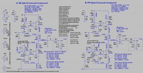
No, i build circuit B.
I promised Calvin to keep the discussion of this buffer in the original thread.
There you find all information.
I promised Calvin to keep the discussion of this buffer in the original thread.
There you find all information.
Difference is the Rail to rail cap, making additional Rc Rail filtering..
I would think that 'SE' vs 'PP' is a hint 🙂 http://www.diyaudio.com/forums/analogue-source/220309-masterpiece-69.html#post3460408
Yes, circuit B is push-pull. Here the CCS is driven too. That gives double the output current. I would call that a Taylor buffer.
In circuit A the CCS just delivers constant current.
I found that circuit B sounds better although it did measure the same when 10kOhm is the load.
In circuit A the CCS just delivers constant current.
I found that circuit B sounds better although it did measure the same when 10kOhm is the load.
Ohh I see now how the lower current source is modulated, nice thinking, could be why it sounds so expansive and dynamic.
Yes, that modification made the sound much more robust without loosing fine details.
yeah I bet it does as the lower side is now active part in the output contribution thus increasing drivability at no cost compared to circuit A.
Very smart indeed!
Last edited:
It is also non switching. When the BJts run out of steam there are still the J-Fets.
Signal path is super simple too for the micro details.
This is a sledgehammer with class.
Signal path is super simple too for the micro details.
This is a sledgehammer with class.
All,
after more analisys and listening tests I am trying to determine if the problem I have heard is just due to something being faulty on my board or not.
It seems to be an overaload margin problem.
What I hear is clipping on high peaks. At first I thought it was my cartridge bu then I put an inverse RIAA and iPad and it shows the same problem.
So I put the phono back on the bench and I was unable to find any problem with it.
However I noticed that at high frequency the clipping looks pretty ugly.
Also I have noticed that the two halves are not so symmetric although I am using dual matched packages for the input stage.
Any thoughts on this? I will run some simulation to double check some parameters.
Are you using both outputs in balanced or do you use only one output ?
I am running full balance from input to output.
So yes both outputs.
How can we improve the clipping behaviour? It is something I have no clue how to solve.
I am planning on doubling up the input device and running about 35mA on the mirror that drives the RIAA.
- Status
- Not open for further replies.
- Home
- Source & Line
- Analogue Source
- Masterpiece