😀 😀 😀
But seriously, I can't make that circuit work for some reason.
Have you tried yourself to simulate it?
Did you succeded?
But seriously, I can't make that circuit work for some reason.
Have you tried yourself to simulate it?
Did you succeded?
Stefano, have you tried to make both voltage sources at the input positive ?
I just tried all 4 combinations for the 2 input generators, but it doesn't seem to work. 😕
There was a guy, i think his avatar is Elso Quack, that worked with this circuit.
I think he has his own blogg now so you have to find him.
I think he has his own blogg now so you have to find him.
I would make it like a two stage.. first stage with the high-cut part of riaa between the legs...then folded over in the opamp.. with a local feedback there making the base part active.
You generators are canceling... so both legs are seeing the same signal. need to phaseshift one 180 degrees.
You generators are canceling... so both legs are seeing the same signal. need to phaseshift one 180 degrees.
I would make it like a two stage.. first stage with the high-cut part of riaa between the legs...then folded over in the opamp.. with a local feedback there making the base part active.
You generators are canceling... so both legs are seeing the same signal. need to phaseshift one 180 degrees.
Interesting concept.
Otherwise is it possible top create out of this a differential folded cascode with transimpendance RIAA? something to think about.
If I pass the hump to simulate the plain scheme I can try to work that around.
For the generators, they are out of phase.
He is moderator there. He talked about that circuit too here on DIYAUDIO in the old times.
Sorry, i am not very helpful at the moment. Have a ton to do.
Sorry, i am not very helpful at the moment. Have a ton to do.
He is moderator there. He talked about that circuit too here on DIYAUDIO in the old times.
Sorry, i am not very helpful at the moment. Have a ton to do.
I will try to look for it...if and when you have chance if I haven't found it yet and you have instead, please post it on here 🙂
Thaankkss
I only remember that he posted that this is a superior circuit.
and it looks so interesting. Do you remember other details on the post? like title fo the thread?
I tried to google but I was unable to find anything related!
You can go to the members area and find his name. Then you can find his posts. Sorry but i do not have the time to do the detective work unless you pay me (-:
ahahahahah!! I will do the detective although I have no license so I hope I won't brake the law!!!
was his name by chance:
Elso Kwak?
was his name by chance:
Elso Kwak?
Maybe you can start here :Re: 2SK117 or 2SK170 input stage?Better use 2SK389 - Elso Kwak - Tweakers' Asylum
That is the same post I was looking at I think.
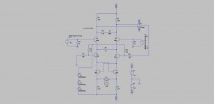
On that post there is a mention on page 6 that change the 3.9 Zener with string of diodes leads to same low noise and same sound quality.
So I figure out what the circuit was missing: the 3 LEDS.
Why is that I don't understand....but here it is....
On that post there is a mention on page 6 that change the 3.9 Zener with string of diodes leads to same low noise and same sound quality.
So I figure out what the circuit was missing: the 3 LEDS.
Why is that I don't understand....but here it is....
Attachments
I am in the meantime shaping out in my mind how masterpiece can be laid out.
These are my two cents feel free to comment.
I have noticed that it is very hard to design an MC stage with enough gain with relative simple circuit (except for paradise) or at least with the different circuits we explored so far I am sure there are better ways out there I simply don't know them.
Anyhow this latest circuit seems to be very suitable for a mc section with cascoded monolithic 2SK389 and a gain of 49dB roughly. I will have to find a way to make it fully differential though.
This stage followed by a passive differential 75uS time constant feeding masterpiece rev 7 with only n-ch with maybe one or two 2sk389 (if a gain of 35-40 dB can be reached out that way) with trans z rest of the RIAA in fully balance configuration.
This is my thought so far, thus a 2 gain stages with split RIAA which circles back out with the first disclaimer in my first post 🙂 .
What do you guys think? Does this idea have the potential for being a very low noise and distortion mc phono stage?
Yes, i would go for a two stage design. I would do the 75usec transimpedance first and then the rest active ( feedback ).
just like I Said..🙂 two stage...high cut between the legs and active feedback in the second op-amp stage... let the first stage run without the feedback, as the signal levels are so low the distortion would be fairly low, noise sort of highish. (if you use the LSK or SK fets. (interfet would be interesting and lower in noise)
second stage would then have the base shelf as a part of the feedback network..
what you would then have is a floating input. (not balanced) and a single-ended output. Performance would in my objective be good. (One shot is still a more novel circuit.)
second stage would then have the base shelf as a part of the feedback network..
what you would then have is a floating input. (not balanced) and a single-ended output. Performance would in my objective be good. (One shot is still a more novel circuit.)
- Status
- Not open for further replies.
- Home
- Source & Line
- Analogue Source
- Masterpiece