The primary side of the transformer is the low voltage side internal windings attached to the green & black wires. The secondary side of the transformer is the high voltage winding side stepped up seventy times with the blue & brown wires attached and the red wire is the center tap ground. The method of hook up for the active crossover seems correct just make sure your high voltage bias board is working and the 15M-ohm resistors are not shorted open.
So I'm still using the old bias board? Are these 15 ohm resistors the tiny stripped pill like things or the larger bubble like things. Also, what do I do with the smaller transformer like thing in the middle of the board....do I need to test it?
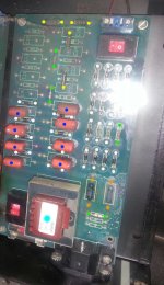
You will need to use this high voltage bias board. Before working on the bias supply make sure it's been unplugged overnight to dissipate any high voltage charge. First check the glass fuse below the transformer to see if it has continuity then you should check the power resistors indicated with the orange colored dots feeding into the transformer. I believe they should both measure around 1800-ohms each. The high voltage output resistors are on top of the pc board marked with yellow dots and should measure around 10M or 15M-ohms each and it's very common for these to short open. There are jumpers marked with green dots and should measure 0-ohms each. The diodes are all marked with white dots and they should only have current flowing in one direction only. You can use your multimeter on these if it has a diode test function. The blue dots are your capacitors and they should measure .01uF each but you'll need an LCR meter to test these. As for the transformer with the teal color dot just make sure it has 115V input and six or twelve volts feeding into the high voltage multiplier section or you can ohm the windings for continuity as you did with your audio step up transformer.
.
.
Attachments
X83
WOW, lots of measuring with tools I don't have. ..is there an easier way to measure what is coming out of the red and blue wires when the board is plugged in...or will this just kill me?
WOW, lots of measuring with tools I don't have. ..is there an easier way to measure what is coming out of the red and blue wires when the board is plugged in...or will this just kill me?
Actually there's a typo on the capacitor value which should be 0.1uF and the transformer voltage should be about double that of the input voltage. I've yet to find a good way to check the 3.5kV output voltage because it's a very low wattage and the high voltage probes don't seem to work.
Yes..........3.5-8KV bias feed is what ML stop at...........
I re-work the ML panels & bias feeds......... an it moves up a littel if the panels get full feed.....
the older bias were higher 4.6kV... but dropet it....for all there panels....even the CLS.....
this is what Jim Powers told me before he left ML.......
RIP Mr powers.........gave me a lot of help with there setups.......... was a good man
Thank you all for your assistance especially, Tyu and X83. At this point I'm still trying to figure out how to determine if the boas board is working properly. Based on my past testing, would it be logical to assume that they are properly working, as I was able to determine that the panels both worked with only one of the back speaker electronics plate....it made the amp overheat but sound was clear and present from the panels and subs. Then, I switched the bias boards only and I got the same results...panels and subs worked but only off one of the same back plate. To me that meant that the crossovers were the problems...one did not work and the other worked but had at least one short....probably several since I was able to test the some resistors and they did not provide and impedance reading. So, since at least one speaker worked whith either bias boards, is it safe to assume that the bias boards are good and I just have problems with the crossover parts? And as mentioned earlier, I can use an external active crossover for this. The reason that I'm trying to determine this is because I don't think I have the specific tools to test it thoroughly as suggested by X83 and Tyu and I would like to know before I purchase an external crossover. Base on my logic, do you guys think that my bias borads are good?
Last edited:
I believe this may be above your skill level with the tools you have. It might be wise to send the boards out and have them checked out professionally. I'm almost certain the high voltage bias boards are not working correctly which caused the overheating of your crossover boards.
X83, how that ??
I suppose your crossover is fried due to too much amp power and/ or clipping, plus one of your panel lost its` ability to carry charge.
Older Sequels often fail in this regard.
If you are lucky, you can recoat them by yourself (Calvins Glue-Formula worked for me perfectly). You can search in the planar forum here for it.
If you manage to open the stator, without tearing the Mylar, you can apply new coating.
I own the Sequel 2 and the ML Odyssey.
The Odyssey has a better coating, more durable.
Mine Sequels also lost their coating.
You really should consider, driving them active, once you are done.
And put a better bass speaker in it (but that's allready finetuning).
Regards Olaf
Taotao
Based on my testing, both panels worked however, I will trying recoating them if they sound weak once I know that the bias boards are working. Did you use the glue and ink method for your Sequels? ...I read that the computer screen spray worked better?
Based on my testing, both panels worked however, I will trying recoating them if they sound weak once I know that the bias boards are working. Did you use the glue and ink method for your Sequels? ...I read that the computer screen spray worked better?
Hi,
sorry I missunderstood.
If your panels both are working; fine.
Yes glue and ink.
I only had to wipe the mixture 3 times on the mylar, before it worked.
For applying, i used a sponge.
My feeling about the durabiltiy of this coating is very good; I imagine the tiny carbon particles being trapped in a very thin layer of glue 🙂
Dunno if the spray is working better. Maybe it's easier to apply an even coat with a spray can?
But the mixture is fullfiling its' purpose, that's all that counts for me.
Beside, it's some fun to fix a problem with such easily to obtain ingredients (at least here --> TESA is a german brand).
I like this DIY spirit ...
Regards
Olaf
Last edited:
Taotao
Thanks for the response. ..if I have to do this later I'll communicate with you. By the way, how long has your coating lasted?
Thanks for the response. ..if I have to do this later I'll communicate with you. By the way, how long has your coating lasted?
three weeks 🙂
edit:
Oh, you mean the original coating? Hmmm....
I bought them secondhand, and they allready startet to sound weak.
I guess the original coating lasted around 8- 9 years.
edit:
Oh, you mean the original coating? Hmmm....
I bought them secondhand, and they allready startet to sound weak.
I guess the original coating lasted around 8- 9 years.
Last edited:
I'd propose you read post number two in this thread as this has been revealed many times.X83, how that ??
I suppose your crossover is fried due to too much amp power and/ or clipping, plus one of your panel lost its` ability to carry charge.
Regards Olaf
I wouldn't recoat the panels unless it's necessary. A good way to see if your bias & panels are working well is to hook up a 1kV 0.1uF capacitor with a neon bulb in parallel connection between the high voltage red wire out of the bias board to the panel in series. If all is well, the neon bulb will flash rapidly at first, and then slow down as the panel charges up, slowing down to something on the order of 1 flash per second for a typical panel. If the neon bulb flashes rapidly at first but never really seems to slow down, there is a short or leakage between the stators and the diaphragm. If the neon bulb doesn't flash rapidly when the power is first connected, there is either a problem with the diaphragm contact, or the coating has deteriorated, or the bias supply has no high voltage output.Taotao
Based on my testing, both panels worked however, I will trying recoating them if they sound weak once I know that the bias boards are working. Did you use the glue and ink method for your Sequels? ...I read that the computer screen spray worked better?
I've read post nr. 2, but I didn't get it.
Why should a faulty bias fry the crossover components?
Why a dead short without bias?
The amp sees the frequency dependent impedance (Z) of the transformater primary, independent from bias.
At higher frequencies, it drops to arround 1,5 ohms, but not zero.
Zero only, if the primary has a short (even then, there's still a cap paralel to a resistor in the signal path)
Maybe I miss something here..
You think some AC from the bias is transfered from secondary to primary and this AC fries the components?
Maybe you could explain to me.
Regards
Olaf
Last edited:
Any amp can be driven into clipping.........to the amp...with out bias.. it looks all most like a dead short!..............................
[all most]....1 1/2ohms is close a nef!............he may think he has a amp that well drive that........i think not!
i have know way of knowing what fried this crossover...just trying to give info to help from him killing more....like his amps......
maybe you can see what going on...?
good luck
[all most]....1 1/2ohms is close a nef!............he may think he has a amp that well drive that........i think not!
i have know way of knowing what fried this crossover...just trying to give info to help from him killing more....like his amps......
maybe you can see what going on...?
good luck
Hi Tyu,
in post2 you say "Looks like the bias is out............if there is No bias... all parts well cook....an get vary HOt..like yours look!"
This would mean, if I unpluck the speakers from the mains (there would then be no bias), and I play music, all parts will be cooked?
Of course not.
Bias is independend from the crossover parts at the primary side of the transformer.
Only one thing I could imagine is a short between primary and secondary; in this case, high voltage from the bias board can pass this shortage and maybe damage something on the primary side.
Ah, I don't know.
It's just my opinion, that the bias boards are not the cause for this disaster.
But what do I know...
taotao says...............
Ah, I don't know...................nor i!................
But one thing i do know...........if any ESL tranfourmer an panel... is driven hard the amp well klip.... without bias on a panel.....the parts in the crossover....an the tranfourmer... well get vary Hot...
you are right.....the speakers could have been un-pluged from the manes....bias may be fine..............
What happen here ....my Crystal Ball broke..cant get parts....................
good luck
Update
I have decided to replace all dead the bad resitors in the crossover part for another $30.00...I should receive these parts in a week. At that point I will have replaced all the caps and resistors in crossover section leaving the bias section in it's original condition. I guess the only parts I did not replace are the two inductors in the crossover. If this works, I will do the same for the other speaker hoping for the best. I'll let folks know what happens.
I have decided to replace all dead the bad resitors in the crossover part for another $30.00...I should receive these parts in a week. At that point I will have replaced all the caps and resistors in crossover section leaving the bias section in it's original condition. I guess the only parts I did not replace are the two inductors in the crossover. If this works, I will do the same for the other speaker hoping for the best. I'll let folks know what happens.
- Status
- Not open for further replies.
- Home
- Loudspeakers
- Planars & Exotics
- Martin Logan Sequel II dead panels