Wow! That's IT! Not exactly the 100 version but plenty of useful projects and info on how things worked and what the parts did. Then I started using the parts to create other circuits/ideas. later, i got a pencil soldering iron and eventually a VOM and scope and made my first test equipment -- a transistor characteristic tester... all with analog meters monitoring every terminal's current flow at different R's etc and then I could calculate the HFE etc. Installed in a red lunch box. Who knows... it might still be at my mothers house somewhere --- she just turned 93 !! I was always impressed by magic and learned some tricks... still do some... electronics seemed like magic to me... something that caught my curiousity to learn how it works.. the trick to it.
Thx-Dick Marsh
Last edited:
I had the time to listen to the amplifier, but as I recently sold my DAC, I had to rely on my m-audio soundcard to do all the listening, so this made the task rather difficult.
Still, I can say that the amp sounds very very promising! It is very natural sounding, with perhaps a touch of warmth, fast and punchy, with excellent reproduction of tones. Soundstage is earthy and expansive, intruments feel real, palpable. I will be able to develop more when I find a proper source.
In the meantime, I made some measurements, here are the results...
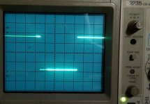
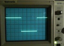
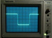
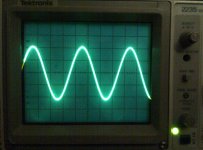
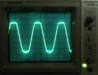
Let's begin with sine/square wave tests on the scope.
From left to right: 10Hz, 10kHz, and 100kHz square wave output. I didn't install the input filter cap to allow full bandwitdh.
Still, I can say that the amp sounds very very promising! It is very natural sounding, with perhaps a touch of warmth, fast and punchy, with excellent reproduction of tones. Soundstage is earthy and expansive, intruments feel real, palpable. I will be able to develop more when I find a proper source.
In the meantime, I made some measurements, here are the results...
Let's begin with sine/square wave tests on the scope.
From left to right: 10Hz, 10kHz, and 100kHz square wave output. I didn't install the input filter cap to allow full bandwitdh.
Attachments
Last edited:
Those are picture perfect square waves. You will like the sound even better with a good DAC, I am sure. Thank you for sharing your results !!
-Richard
-Richard
Thank you for publishing such an interesting design. I am impressed with the performance of the circuit, especially in relation to its simplicity.
Now I am curious how the performance could be improved further, did you manage to build the 12 transistor version you mentioned in your article?
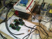
Below, sine wave and clipping behavior...
Now I am curious how the performance could be improved further, did you manage to build the 12 transistor version you mentioned in your article?
Below, sine wave and clipping behavior...
Attachments
Hi All,
CafeNoir was right nearly all my are within 20% and I have 2 sets within less than 10% of each other. 🙂
I hve built 2 PSUs for the amps and have (at last) got round to soldering all the resistors on Samuel's boards also matched the 2sa1930/2sc5171s. Now about to order the caps, some more 2sa/2sc (just to see if I can get any closer matches) and the rest of the semi cons from Mouser (now I have the min order value).
I will be using AAVID THERMALLY ML26AAG heat sinks and mounting the SA/SC s horizonally to the back of the sinks to keep the e b c configuration correct. i.e. mount them with correct config verticaly, bend legs thro 90 degs and mount heatsinks to them with the sides pointing upwards. The sinks then overhang the board a bit but I have plenty of space.
I am using the boards the correct way up too (liked all the clear componet printing) and so I am reversing SA/SCs mounting Sounds more complicated than it is I will post some pix when all sorted.
So onward and upward
Pingushome
Hi,
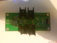
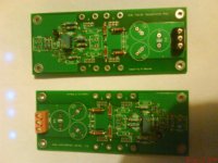
Construction so far, have to reorder R11/14 and still waiting Mouser order for the caps etc.
Pix not great on my phone.
The second is how the heatsinks will mount when the devices are soldered up and mounted to the bottom of the sinks. They will then be clear of any other bits on the board
Construction so far, have to reorder R11/14 and still waiting Mouser order for the caps etc.
Pix not great on my phone.
The second is how the heatsinks will mount when the devices are soldered up and mounted to the bottom of the sinks. They will then be clear of any other bits on the board
Attachments
Note the results in #40 are for 33 Ohm load and therefore higher Z loads, will result in even lower THD.
-RM
-RM
Folks from Burson sent me this review of a bunch of headphone amplifiers -- the Marsh Headphone Amplifier would certainly be in the first ranks: Innerfedility Soloist Review Summary
Thank you for publishing such an interesting design. I am impressed with the performance of the circuit, especially in relation to its simplicity.
Now I am curious how the performance could be improved further, did you manage to build the 12 transistor version you mentioned in your article?
...
I built the 12 transistor circuit on a prototyping board with jumpers all over the place. It was only when I saw the complexity building with less and less improvement, that I decided this is not the best approach to design and started over.
I have been thinking about what could be done to improve it and what the improvement could be..... nothing firm yet has come to mind.
Thx-RNMarsh
Last edited:
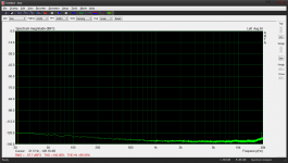
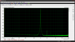
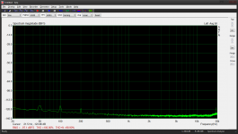
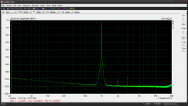
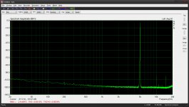
Thanks Richard, here are some more measurements that show great performance again. Those were taken at full gain (x4), so the noise floor of the soundcard is raised a bit. See the measurement with input shorted to appreciate the real noise floor. The headphone amplifier was powered with a sulzer type regulator.
Amplifier output load is 1kOhms. Performance is a bit worse at 30Ohms, because I forgot to adjust R9 with low impedance load... I will have to look into it.
All measurements were taken with the M-Audio Firewire Audiophile soundcard. They are linear averaged over 50 samples.
1. M-audio soundcard noise floor
2. M-audio soundcard loop-out 1kHz FFT at aprox. 0.75V
3. Marsh headphone amp noise floor (input shorted)
4. Marsh headphone amp 1kHz FFT at aprox. 0.75V
5. Marsh headphone amp 5kHz FFT at aprox. 0.75V
Attachments
-
 M-Audio FW Audiophile_noise floor - avg 50.png69.8 KB · Views: 913
 -
 M-Audio FW Audiophile loop - avg 50.png64.1 KB · Views: 898
 -
 Marsh headamp_noise floor - avg 50.png70.2 KB · Views: 882
 -
 Marsh headamp - final - avg 50.png64.1 KB · Views: 885
 -
 Marsh headamp - final - 5kHz - avg 50.png62.6 KB · Views: 861
Can you use a notch filter on your ADC input to get more accuracy in the sub- 100-110dB area?
I think you are working up against the ADC measuring system and also need a cleaner input sine wave to get accurate harmonic measurement.
Your amp measured results shows others it can be done by someone other than myself and get great results. Next? Music listening?
Enjoy!
-Richard Marsh
I think you are working up against the ADC measuring system and also need a cleaner input sine wave to get accurate harmonic measurement.
Your amp measured results shows others it can be done by someone other than myself and get great results. Next? Music listening?
Enjoy!
-Richard Marsh
Last edited:
Rmoore might be good for a notch filter/ADC for L.A.
The Distortion Magniifer, i believe needs more gain from the headphone amp/DUT to work (> than X10/20dB).
-RM
The Distortion Magniifer, i believe needs more gain from the headphone amp/DUT to work (> than X10/20dB).
-RM
Jackinnj or anyone who can answer,
I ordered the boards and kit from Tech-DIY.
Also, ordered the Linear Audio Volumes 3, 4, and 5 (these will probably take some time to get here).
What is the size of the PC board? and how much heat sinking is required (internal individual heatsinks or will the side wall of the chassis do)?
I would like to order a chassis, transformer and have all the pieces arrive at once to keep the momentum going.
Was wondering if this will need to be in 2 chassis or can it all fit in one and what sizes they or it would need to be.
Rush
Thanks Richard, here are some more measurements that show great performance again. Those were taken at full gain (x4), so the noise floor of the soundcard is raised a bit. See the measurement with input shorted to appreciate the real noise floor. The headphone amplifier was powered with a sulzer type regulator.
Amplifier output load is 1kOhms. Performance is a bit worse at 30 Ohms, because I forgot to adjust R9 with low impedance load... I will have to look into it.
Nice results so far -- and do you have it all in a box/chassis to show us?
-Richard
I just got the new Audio-Precision 2722 up and running. I will be able to do more detailed distortion tests (multi-tone, IM etc).
And, as a comparison against the other analyzers used (sound cards, eMu, QA400, etc).
Thx-RNMarsh
And, as a comparison against the other analyzers used (sound cards, eMu, QA400, etc).
Thx-RNMarsh
Can you use a notch filter on your ADC input to get more accuracy in the sub- 100-110dB area?
Bob Cordell's "Distortion Magnifier" in LA volume 1 is a good remedy
Good ideas, I will look into it.
Nice results so far -- and do you have it all in a box/chassis to show us?
Not yet. I plan to do everything from scratch using aluminium profiles. I have made a few sketches, but it will wait until I have decided on the power supply to use (and dimensions). One thing for sure: it will be a two chassis design, with transformers in one box and PSU/signal boards in an other, in order to allow lowest noise possible.
I just got the new Audio-Precision 2722 up and running. I will be able to do more detailed distortion tests (multi-tone, IM etc).
And, as a comparison against the other analyzers used (sound cards, eMu, QA400, etc).
Wow, please show us some results when you have the chance.
- Home
- Amplifiers
- Headphone Systems
- Marsh headphone amp from Linear Audio