The component kits i'm sending out now include 2SD669AC and 2SB649AC output transistors -- rather than the MJE210G/MJE200G. i have about 25 kits of the semiconductor components including the 2N5457/2N5460's matched.
The component kits i'm sending out now include 2SD669AC and 2SB649AC output transistors -- rather than the MJE210G/MJE200G. i have about 25 kits of the semiconductor components including the 2N5457/2N5460's matched.
Hi,
Will these kits be suitable for CafeNoir's boards for the HA and will I need two for two boards or are the kits "stereo"?
Finally can you pls let me know the cost incl shipping to the UK mainland (actually then BEST part of the mainland.......WALES 😀😀_)
Thanks
Martin
Afaik The circuit is the same, only the pcb is different.
I have instead a question for jackinnj: have you listened to both output stage transistors?
If so, what's your opinion? If not, can you send me a pair of the hitachi 🙂
I have instead a question for jackinnj: have you listened to both output stage transistors?
If so, what's your opinion? If not, can you send me a pair of the hitachi 🙂
Afaik The circuit is the same, only the pcb is different.
I have instead a question for jackinnj: have you listened to both output stage transistors?
If so, what's your opinion? If not, can you send me a pair of the hitachi 🙂
You need 8 -- i have ur address!
I became intrigued with them because of the Randy Slone articles -- they have higher hfe, higher ft -- but are no longer in production -- i have beacuoup and will send you a set!
-- i have beacuoup and will send you a set!
Thanks, I definitely want to try them 🙂
I have 3pin sockets, so I will also try my favourites (Rohm 2SD1763/2SB1186).
In a couple weeks I should finally start to build this amp.
Richard / Jack,
I´m a bit intrigued in the use of Panasonic resistors (metal oxide) seen and described in Jack´s BOM and boards.
I´ll appreciate if you guys could elaborate a bit more on the subject and the possibility of using metal film instead.
Thanks,
Rob.
I´m a bit intrigued in the use of Panasonic resistors (metal oxide) seen and described in Jack´s BOM and boards.
I´ll appreciate if you guys could elaborate a bit more on the subject and the possibility of using metal film instead.
Thanks,
Rob.
Richard / Jack,
I´m a bit intrigued in the use of Panasonic resistors (metal oxide) seen and described in Jack´s BOM and boards.
It's simple -- Nelson used them in various First Watt designs -- they are inexpensive (availble from Digikey) and compare quite favorably measurement-wise with the more expensive variety. I claim no prize for originality.
Output transistors
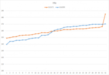
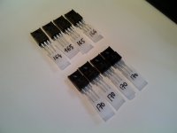
I wanted to try 2sc5171/2sa1930 transistors pairs for the output stage, as they have great characteristics, and are available on Mouser.
I am pleasantly surprised with the results: the whole batch has an Hfe within 10-15%. More importantly, NPN and PNP have very close characteristics (see graph below).
They have clearly become my favourite devices for the job: Beta and Ft is higher than MJE200/MJE210, and they can sustain higher voltage too. Flat Hfe as a function of current.
Really great transistors in my opinion.
The only issue is they have reversed pin, so they must be soldered backwards...
Attachments
Hi CafeNoir,
I am still gathering the bits for your boards, work permitting, but funnily enough I have these transistors as they are used in pairs in the JLH Ripple Eater over on Gregs site
Greg's Web Site
So I will use them (Remembering to revers them). Will all the other componets work with them as your BOM?
Martin
Hi CafeNoir,
I am still gathering the bits for your boards, work permitting, but funnily enough I have these transistors as they are used in pairs in the JLH Ripple Eater over on Gregs site
Greg's Web Site
So I will use them (Remembering to revers them). Will all the other componets work with them as your BOM?
Martin
Sure,
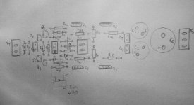
when you flip the board, all transistors will be reversed (except the output transistors, since their pins are already reversed)
Here is a sketch with component placement on the flipped board to prevent errors while soldering:
Attachments
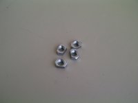
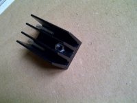
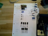
Finally, I managed to finish the assembly of the boards. One issue that I had was the Aavid-Thermalloy 581002B02500G heatsins are #6-32 tapped, which does not fit the to-128 package holes ( - If anyone knows were to find M3 tapped version of those heatsinks, I would be very interested).
The solution I came up with was to file small M3 nuts using a dremel, and fit them on the other side of the sink. That way the transistor can be securely attached with a regular M3 screw. 🙂
The solution I came up with was to file small M3 nuts using a dremel, and fit them on the other side of the sink. That way the transistor can be securely attached with a regular M3 screw. 🙂
Attachments
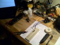
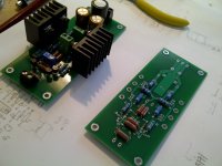
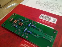
Construction pics...
Attachments
-
 IMG-20130413-00187.jpg202.8 KB · Views: 425
 -
 IMG-20130331-00161.jpg269.3 KB · Views: 370
 -
 IMG-20130331-00160.jpg289.5 KB · Views: 423
 -
 IMG-20130331-00157.jpg245.1 KB · Views: 414
 -
 IMG-20130330-00144.jpg205.2 KB · Views: 675
 -
 IMG-20130330-00143.jpg160.2 KB · Views: 679
 -
 IMG-20130413-00189.jpg184.1 KB · Views: 512
Construction pics...
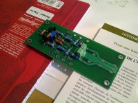
Hi, reason why you mounted that diode in the middle?
Since I use only 3 diodes for the bias, mounting this way reduces the trace length compared to putting a jumper on one diode's place.
Last edited:
Since I use only 3 diodes for the bias, mounting this way reduces the trace length compared to putting a jumper on one diode's place.
Hi,
Thanks for the pictures and layout sketch, your draughting skills are far better than mine, it's all a bit clearer now. I take it that you are building on the underside of the board in the last four pictures and that the top (correct) side of the board is the one with the center diode on it, picture three? (keeping in mind the transistor CEB pins)
Not sure about that center diode tho do I need to add it? 😕
All the best
Martin
Did quite a bit of simulating the circuit and some hands on experimentation (again). One of the best tweaks you can do is to have the ability to adjust R9 or R10. Second, matching the sets of output devices to +/-5% helps as well, and the JFETs +/-5% Idss.
One of the best tweaks you can do is to have the ability to adjust R9 or R10.
Adjust how much? I dont particularly like trimpots
... I dont particularly like trimpots
But you do want the best sound, presumably. Tough call 😉
jan
- Home
- Amplifiers
- Headphone Systems
- Marsh headphone amp from Linear Audio