Fortunately, not a risk given many factors including relatively low occurrence rate (1:1,000 to 1:2,000), and being pre-vaccinated/boosted.
I'm just amazed how well you understand this circuit given it's ridiculous number of components. Rather the exact opposite of many designs including those by N. Pass.
Cheers,
Greg
I'm just amazed how well you understand this circuit given it's ridiculous number of components. Rather the exact opposite of many designs including those by N. Pass.
Cheers,
Greg
Wonder if the standby switch on this board? I have a problem on Mark Levinson 532 that the standby switch does not work. However, when I connect to computer with network to reset everything, then it works for a few times, then it comes back the same thing. So have been using Trigger with preamp to turn it on.
This previous generation of ML amps don’t have a stand by switch.
I agree that ML doesn’t even try to keep things simple.
Things like discrete regulated power supplies, soft start, shut down and soft clipping circuits, very complex overload protection, over temp sensing and output DC monitoring are a number of things that add a lot to complexity.
Most ML equipment was never designed with easy repair in mind making a repair at an authorized service centre very expensive.
That’s why I took the hard way and gathered the knowledge by reverse engineering my ML20.6 at a time no circuit diagrams were available, not to make money, but just to be able to do the repair by myself.
The 20.6 had teflon PCB’s that where like chewing gum and had to be serviced almost every year, making me to decide to develop my own boards based on smd technology and higher integrated level of components.
At a later stage it was a surprise to see that all ML amps are very closely related and are still using similar “family” technolog up to class D.
Hans
Ah, yes - I remember you telling me you designed it for SMDs. Lots of fiddly soldering there, Hans, but they look great. I'm sure the measured performance is better than the 30+ year old boards!


Here you are
Hans
.
amazing job! How does it sound compared to the original?
Sooner or later all teflon ML PCBs will need replacement. Restoring my 23.5 I found horrible previous repair job that really damaged the traces and the boards.
Yes, the quality of those 23.5 boards are not very ruggedized and are easily damaged.
That’s why I offered 23.5 users to produce a more service friendly and modernized set of PCB’s, but just until now there’s only one person interested.
And because it has to be plug compatible, special hardware has to be produced to let everything fit.
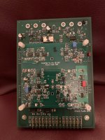
To give you an idea, the set would roughly look like in the image below.
A base board with a pluggable modern amplifier board on top that can be simply removed without any soldering.
Hans
P.s. Yes I’m very happy with the sound of my amp, to my very subjective opinion it’s the best amp I ever heard including the original 20.6.
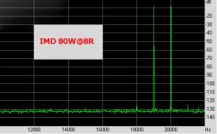
But it is quite a different desing, a 26dB gain voltage amp followed by a 0dB gain current amp with dual nested feedback resulting in a very low distortion.
.
That’s why I offered 23.5 users to produce a more service friendly and modernized set of PCB’s, but just until now there’s only one person interested.
And because it has to be plug compatible, special hardware has to be produced to let everything fit.
To give you an idea, the set would roughly look like in the image below.
A base board with a pluggable modern amplifier board on top that can be simply removed without any soldering.
Hans
P.s. Yes I’m very happy with the sound of my amp, to my very subjective opinion it’s the best amp I ever heard including the original 20.6.
But it is quite a different desing, a 26dB gain voltage amp followed by a 0dB gain current amp with dual nested feedback resulting in a very low distortion.
.
Attachments
Here you are
Hans
.
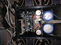
Very interesting. That would be the bottom board of the 23.5? How would you connect the output transistors and the aluminum bars?
I'm envious, Hans.
I can't say the 27 is the best amp I've heard or the best amp I have. It sounds good but not as articulate as some of my other amps, though the work I conducted on it did improve the sound.
I can't say the 27 is the best amp I've heard or the best amp I have. It sounds good but not as articulate as some of my other amps, though the work I conducted on it did improve the sound.
It would be a new board but have the same size but now with a ground plane and thicker copper traces.
The bars are not aluminium but tinned red copper which have either to be produced or taken from the old board which is relatively easy to do with a heat gun.
All transistors sitting on those large heatsinks will of course have to fit exactly the same way to the new PCB, just like all cables and copper bars, completely plug compatible.
Hans
hi Hans, bad news unfortunately. I reassembled the left channel main board and connected everything as you told me. with the short between P1006 and P1007 voltage across the two 150R resistor was 1V (same as the other channel I previously tested), voltages were all good (± 85 V on the large unreg caps and ±84V for Vreg), so I removed the short between P1006 and P1007. When I did so I measured voltage across the two 150R resistors and it was 4Volts on both positive and negative sides. Voltage across on of the 0,1Ohm resistors was 0V... I disconnected everything and was looking for shorts on the PCB but my meter is acting crazy and is totally unrealiable for resistance measurments, will need to get a new one. I did use the meter to check the solderings on the heatsink transistors (since it cannot be checked visually) but at this point with the meter broken I might have missed some shorts there. all heatsink transistor measured good before assembling everything back
Last edited:
Be glad that most likely you did not blow up anything.
So next step is, tell me what voltage you see on P1006 and P1007 with short circuit removed.
From there we will go step by step.
Hans
So next step is, tell me what voltage you see on P1006 and P1007 with short circuit removed.
From there we will go step by step.
Hans
Thank you Hans for being reassuring and for assisting me. Voltage on P1006 and P1007 would have been the next thing I'd have checked too, just wasn't sure it was safe to leave the amp on. That's good, means that I'm starting to understand something about circuits.
P1007 is -2,6V while P1006 is 0,47V.
P1007 is -2,6V while P1006 is 0,47V.
The power switch in the ML amps is a well kept secret, I never took one apart and it can’t be repaired.
It can be turned off from the outside by heatsink temp or DC at the LS output but turn on is controlled by factors like how much energy is still in the large supply caps and also by an internal ntc based circuit that has to cool down before it can activate its internal turn-on relay
So when the bias currents in the power transistors, discharging the power supply caps, are still o.k. I wouldn’t bother about the switch-on delay.
I’ve seen this in several 23.5 amps and it does not affect a proper functioning in any way when it’s finally on.
Hans
I have a Proceed amp2 (made by Mark Levinson at the Madrigal house). The very jumbo power button won't engage or disengage. Unless its pressed a certain way. Otherwise it clicks and reverts back to current setting with the audible "click".
Seems they limited all unnecessary signal path routing. Such as the on/off relay when initially switching the amplifier on, theres sound as soon as you flick the switch (carefully engage it with some personal technique whilst standing on one tippy toe).
I get around the power button thing by simply keeping it tethered to the preamp via 12v trigger wire to activate on/off settings. But I would fix it if parts are still available? I want to track down a parts source for these older ML amps, and there counterparts with Mark Levinson badging. If someone has them to offer and will be so kind.
Last edited by a moderator:
Thank you Hans for being reassuring and for assisting me. Voltage on P1006 and P1007 would have been the next thing I'd have checked too, just wasn't sure it was safe to leave the amp on. That's good, means that I'm starting to understand something about circuits.
P1007 is -2,6V while P1006 is 0,47V.
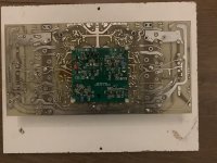
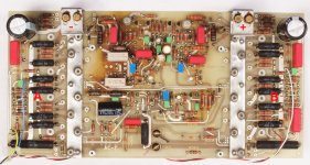
Those voltages are perfect.
Now measure the voltages on the two points that I have marked as A and B.
Hans
.
Attachments
I'm sorry but I have no knowledgde of and circuit diagrams for this amp.I have a Proceed amp2 (made by Mark Levinson at the Madrigal house). The very jumbo power button won't engage or disengage. Unless its pressed a certain way. Otherwise it clicks and reverts back to current setting with the audible "click".
Seems they limited all unnecessary signal path routing. Such as the on/off relay when initially switching the amplifier on, theres sound as soon as you flick the switch (carefully engage it with some personal technique whilst standing on one tippy toe).
I get around the power button thing by simply keeping it tethered to the preamp via 12v trigger wire to activate on/off settings. But I would fix it if parts are still available? I want to track down a parts source for these older ML amps, and there counterparts with Mark Levinson badging. If someone has them to offer and will be so kind.
Hans
- Home
- Amplifiers
- Solid State
- Mark Levinson protection circuit - Need help