 O.k. Now it’s clear what you mean, sorry for not understanding you before.
So in those cases where the protection comes into action at switch off, most likely because of a DC voltage on one of both outputs, switch on has to wait a longer time, but without protection coming into action after switch off, you can switch on much sooner.
Is that correct ?
Is this with load or without load, because it is not at all o.k. that protection comes into action at switch off.
First of all check the bias current on both channels, ca 275mA each.
When that’s ok check both output voltages at switch on and at switch off, preferably with a scope if you have one.
After switch on it should take some 5 to 10 seconds before the output can amplify a signal from its input, till that time it should stay put at zero volt.
After this dead time, voltage offset at the output should be within +/- 10 mV.
At switch off, nothing should happen other than the output stays around zero volt with no spikes or whatever movement.
Let me know what you see.
Hans
Thanks for the reply. Yes without protection I can switch on immediately after switch off.
Are you sure it can be because of DC? I thought the DC sensing circuit was on the rear boards and disconnecting them form the front board didn't solve the protection issue on switch off.
I will definitely do all the measurements when I'll reassemble the amplifier (hopefully 1 week).
However I can tell the amp could play music after about 3-4 seconds from switch on (definitely not 10 seconds), the bias was set low in the past but I adjusted it recently at 275 mA, the DC ouput was 0,1-0,2 mV on right channel and 40 mV at cold and 0,1-0,2 mV at warm up in the left channel.
At switch on I could see some voltage with an old analog meter for a fraction of a second (probably going max to 1 V), nothing on my digital meter and I didn't try hooking up my scope but I will. On my previous speakers (89dB sensitivity) I could se a very minor movement of woofers shortly after switch on, so something is going to the outputs but no major bumps, not even when the protection kicked in.
Triggering the protection through the optocouplers can only be done by either heatsink temp too high or DC on the LS output.
These two are monitored on the OL-2 boards at the back of the amp.
These OL-2 boards can be deactivated by disconnecting the red wires from the big blue caps going to the OL-2 boards.
So when the protection still kicks in with both red wires disconnected on both channels, the cause can’t be DC on the LS output.
But if protection no longer gets activated at switch on, try to find out which channel is causing the trouble.
When however protection is still activated with both red wires disconnected the cause is on the power supply board.
The most likely cause seems to be the cap C324 at the gate of the thyristor that should prevent to trigger the thyristor from spikes.
However, you mentioned to see a 1 Volt bump at start up on your multimeter.
This is absolutely wrong.
Awaiting further results,
Succes
Hans
Triggering the protection through the optocouplers can only be done by either heatsink temp too high or DC on the LS output.
These two are monitored on the OL-2 boards at the back of the amp.
These OL-2 boards can be deactivated by disconnecting the red wires from the big blue caps going to the OL-2 boards.
So when the protection still kicks in with both red wires disconnected on both channels, the cause can’t be DC on the LS output.
But if protection no longer gets activated at switch on, try to find out which channel is causing the trouble.
When however protection is still activated with both red wires disconnected the cause is on the power supply board.
The most likely cause seems to be the cap C324 at the gate of the thyristor that should prevent to trigger the thyristor from spikes.
However, you mentioned to see a 1 Volt bump at start up on your multimeter.
This is absolutely wrong.
Awaiting further results,
Succes
Hans
Thanks then we are on the same page. Will replace c324 since im currently replacing also all the rifa caps in the power supply board.
The 1v at ls output would indicate some failure in the clamping mechanism? Weird thing is I remember it is approximately simmetrical in both channels. Anything I can investigate on the bottom amp boards? After reassembling them and soldering back all the power transistor it will not be possible to work on the boards.
Added to the above:
False triggering of the thyristor wouldn’t make me nervous as long as the intended triggering still functions, leading again to my previous advise in that case, leave it as it is. It’s a lot of work to remove the power supply board just to correct a beauty flaw.
But if the start up and shutt down circuit on the main board malfunctions, that would be a real cause for concern because it directly interacts with the audio signal.
Hans
P.S. I see you already removed the PS board.
Last edited:
The 1v at ls output would indicate some failure in the clamping mechanism? Weird thing is I remember it is approximately simmetrical in both channels. Anything I can investigate on the bottom amp boards? After reassembling them and soldering back all the power transistor it will not be possible to work on the boards.
I will go into my papers and tell you what to check.
This is indeed the problem of this construction with a piggy back board on top.
The whole construction was never made with easy repair in mind and although top quality components were used, PCB’s are not that fantastic and should be treated with great care.
Hans
P.S. I didn’t expect you to be such a skilled person able to take everything apart, that makes the discussions quite a bit easier.
Hi Stefano,
Let me explain the circuit responsible for soft start and shut down.
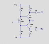
First a basic version of the circuit in the most left image below.
The mosfet at start up is non conducting, causing the two transistors to conduct, thereby pulling P6 and P7 to gnd through the diodes D1 and D2.
This will stop any bias current from flowing through the end stage and at the same time forcing the output to zero volt.
After a few seconds, the mosfet is turned into conduction and the amp will become operational.
At switch off, very soon after the regulated supply is going down, the mosfet goes into off state again, forcing the output back to zero volt.
In both cases this prevents any plops or whatever sounds coming from the speakers at switching on or off but also preventing the protection to become activated.
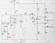
The complete circuit is in the 2nd image below, now disclosing the steering circuit for the mosfet's gate.
However only the numbers in red in the circuit diagram are correct, the others do not correspond with the numbers on your board
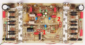
The third image shows the position of the two diodes that are connected to P1006 and P1007 (in the first image called P6 and P7)
Working your way back you can find the two transistors and the mosfet.
When any of these components malfunctions, you have a problem.
These components can be checked in a passive way by removing and testing them.
An active test is a bit more complex but can be done without the piggy back board but with the board mounted on the heatsink and the TO3 transistors in place.
Hans
Let me explain the circuit responsible for soft start and shut down.
First a basic version of the circuit in the most left image below.
The mosfet at start up is non conducting, causing the two transistors to conduct, thereby pulling P6 and P7 to gnd through the diodes D1 and D2.
This will stop any bias current from flowing through the end stage and at the same time forcing the output to zero volt.
After a few seconds, the mosfet is turned into conduction and the amp will become operational.
At switch off, very soon after the regulated supply is going down, the mosfet goes into off state again, forcing the output back to zero volt.
In both cases this prevents any plops or whatever sounds coming from the speakers at switching on or off but also preventing the protection to become activated.
The complete circuit is in the 2nd image below, now disclosing the steering circuit for the mosfet's gate.
However only the numbers in red in the circuit diagram are correct, the others do not correspond with the numbers on your board
The third image shows the position of the two diodes that are connected to P1006 and P1007 (in the first image called P6 and P7)
Working your way back you can find the two transistors and the mosfet.
When any of these components malfunctions, you have a problem.
These components can be checked in a passive way by removing and testing them.
An active test is a bit more complex but can be done without the piggy back board but with the board mounted on the heatsink and the TO3 transistors in place.
Hans
Attachments
Last edited:
Added to the above:
False triggering of the thyristor wouldn’t make me nervous as long as the intended triggering still functions, leading again to my previous advise in that case, leave it as it is. It’s a lot of work to remove the power supply board just to correct a beauty flaw.
But if the start up and shutt down circuit on the main board malfunctions, that would be a real cause for concern because it directly interacts with the audio signal.
Hans
P.S. I see you already removed the PS board.
Thanks again for your help. I think you were right about C324 as I tested it and it appears to be faulty. Yes I removed the PS board because I wanted to replace the cracked RIFA paper caps that can go bad and explode (better sooner than later). I am skilled enough to take everything apart but wasn't able to figure the circuit out and point to C324 as the faulty component.
The protection circuit seem to work well otherwise, since I once tried to turn on the amp with both channels disassembled and protection didn't let me do it. Probably because the disconnected wires from the amp boards to the OL-2 boards triggered the signal to the protection circuit (I think normally the thermal sensor is supposed to be shorted and disconnecting it's wires opens the circuit right?). Disconnecting the wires from the OL-2 to the PS board allowed switch on. Anyway it seems the protection is functional.
I know am worried about the turn on and turn off spike protection mechanism that is on the amp boards that could be faulty, but would be very hard to diagnose. The amp sounded just great so the audio path is intact I think. Possible that the large filter caps initially failing could be causing such small transients on the outputs during switch on/off?
I have ordered replacements for them as well but will ship in a few months.
Added to the above:
False triggering of the thyristor wouldn’t make me nervous as long as the intended triggering still functions, leading again to my previous advise in that case, leave it as it is. It’s a lot of work to remove the power supply board just to correct a beauty flaw.
But if the start up and shutt down circuit on the main board malfunctions, that would be a real cause for concern because it directly interacts with the audio signal.
Hans
P.S. I see you already removed the PS board.
Hi Stefano,
Let me explain the circuit responsible for soft start and shut down.
First a basic version of the circuit in the most left image below.
The mosfet at start up is non conducting, causing the two transistors to conduct, thereby pulling P6 and P7 to gnd through the diodes D1 and D2.
This will stop any bias current from flowing through the end stage and at the same time forcing the output to zero volt.
After a few seconds, the mosfet is turned into conduction and the amp will become operational.
At switch off, very soon after the regulated supply is going down, the mosfet goes into off state again, forcing the output back to zero volt.
In both cases this prevents any plops or whatever sounds coming from the speakers at switching on or off but also preventing the protection to become activated.
The complete circuit is in the 2nd image below, now disclosing the steering circuit for the mosfet's gate.
However only the numbers in red in the circuit diagram are correct, the others do not correspond with the numbers on your board
The third image shows the position of the two diodes that are connected to P1006 and P1007 (in the first image called P6 and P7)
Working your way back you can find the two transistors and the mosfet.
When any of these components malfunctions, you have a problem.
These components can be checked in a passive way by removing and testing them.
An active test is a bit more complex but can be done without the piggy back board but with the board mounted on the heatsink and the TO3 transistors in place.
Hans
Thank you so much for the explanation, I had read some about it in the available 27.5 service manual, but wasn't sure about it's actual implementation in the 23.5 since I dont' have documentation.. I can definitely check passively and actively ( in this case I believe I should connect the ground blue wire that is normally connected to the AC7.5 board directly to the P10010-P1009-P1011 pins right?).
One interesting fact, I believe the board you showed is a later revision, mine is probably earlier and doesn't have the 470 uf capacitor and the 4,32k resistor and the 1n4936 diode connected to its negative terminal, nor the P1012 pin to the upper board. However these revisions have been at some point implemented by someone (picture on this page L'Audiotecnico: Mark Levinson - N°23.5). I see these components are connected to the diode you circled in your picture, do they have something to do with the circuit you described. The 470 uf cap doesn't look good (initial bulging) and I have replaced it already.
You are right that many versions do exist, with additional components, with different components etc., etc.
But the general issues are similar and the alterations are rather random and removed or replaced at a later stage.
I can't tell the reason, nor the effect these mods had.
I have even repaired amps with 2 generations of boards.
When you are ready, I can tell you how to actively test the slow start circuit.
Normally, passively testing the 2 diodes and the 2 transistors will do.
Hans
ok great, thanks.
I have actually left channel fully disassembled and right channel still mounted on the heatsink (only the bottom board, upper board disassembled). So I can test passive the 2 diodes and 2 transistors on the left channel, then as soon as I'm done with the power supply board I can test active right channel before disassembling it.
Will tell when I'm ready, thanks again.
Stefano,
When you want to test the soft start circuit without the AC 7.5 board on top, you will need two 6k8 10Watt resistors per channel.
And when you want some safeguard you will also need two 150R 50Watt.
resistors.
When you want to proceed with this, I will tell you how to connect all this.
Hans
When you want to test the soft start circuit without the AC 7.5 board on top, you will need two 6k8 10Watt resistors per channel.
And when you want some safeguard you will also need two 150R 50Watt.
resistors.
When you want to proceed with this, I will tell you how to connect all this.
Hans
Stefano,
When you want to test the soft start circuit without the AC 7.5 board on top, you will need two 6k8 10Watt resistors per channel.
And when you want some safeguard you will also need two 150R 50Watt.
resistors.
When you want to proceed with this, I will tell you how to connect all this.
Hans
Hello Hans, I reassembled the PS board and got the resistors. I am ready to test the right channel.
I have one more question/doubt. Having tested the power supply board with main amp boards disconnected i then had to discharge the filter caps and noticed there is some leakage with the power switch off but power cord connected as the filter caps charge back to about 2 volts. I disconnected the power switch and measured leakage current of the power switch with a meter and it’s 2microamps (I guess normal?). But disconnecting the power switch and leaving the power cord connected there is still leakage since the filter caps still charge back to about 2 volts, so I think it is the orange drop capacitor in parallel with the power switch or maybe some induced currents from the messy wiring? Not sure if it is normal. I can’t measure leakage current from the capacitor as I would have to disassemble the PS board again to desolder the capacitor so I’m not going to do that unless I was sure it is not normal. With power cord disconnected after discharging all the caps they stay at about 500mv
I measured again the voltages with amp switch off and power cord connected:
1- with power switch connected (but off) Vcc unreg caps are ~ 2V (both channels both positive and negative); Vcc reg caps are ~3V (both channels both positive and negative)
2- with power switch disconnected (power cord connected) Vcc unreg caps are ~0,9V and Vcc unreg caps are ~ 2V.
So both the power switch and the 0,047uF capacitor are laeking some current. This is with both channels amp board disconnected. Are these normal values?
Hi Stefano,
I wouldn't worry to much about this minimal leakage current.
Before connecting anything at all, you have to discharge the 4 big blue caps !!
Now testing the amps without the upper board, have the amps horizontally with only the two LS cables connected to the amp (resp P301 and P302), now you will have to connect the gnd wire of the Pre Reg caps with a piece of wire to P1009,P1010 and P1011.
Connect the +/- Vcc Pre Reg to P303 and P404 (resp. ca +/- 117V), and also
connect P1006 through the 6K8 10Watt resistor to the +Vcc Pre Reg and P1007 through a 6K8 10Watt resistor to the -Vcc Pre Reg.
Then through the two 150R resistors connect the amp from the two big bars to resp +Vcc unreg and -Vcc unreg (+/- ca. 83 Volt).
I'll come back later, but I'm running out of time now.
Hans
Hi Stefano,
I wouldn't worry to much about this minimal leakage current.
Before connecting anything at all, you have to discharge the 4 big blue caps !!
Now testing the amps without the upper board, have the amps horizontally with only the two LS cables connected to the amp (resp P301 and P302), now you will have to connect the gnd wire of the Pre Reg caps with a piece of wire to P1009,P1010 and P1011.
Connect the +/- Vcc Pre Reg to P303 and P404 (resp. ca +/- 117V), and also
connect P1006 through the 6K8 10Watt resistor to the +Vcc Pre Reg and P1007 through a 6K8 10Watt resistor to the -Vcc Pre Reg.
Then through the two 150R resistors connect the amp from the two big bars to resp +Vcc unreg and -Vcc unreg (+/- ca. 83 Volt).
I'll come back later, but I'm running out of time now.
Hans
Thank you, I'll be waiting.
Anyhow, I did some further measurements on the PS board before hooking up the amps and I found 120VAC on the front panel chassis! (60VAC with the power switch off)...then I hooked up the front panel chassis to the main chassis with a cable (it was disassembled before) and I got 0 VAC..measuring current through this cable showed 0,1 microAmps... is this normal behavior? I don't think so. I double and triple checked all the wiring. DC voltages seem ok (±86-87V for unregulated lines and ±117-118 V for pre reg lines).
Last edited:
I think 100nA is nothing, but you have to assemble the whole chassis together and always connect the amp through a mains cable with PE.
Between the alu bar on the big blue caps and PE you should measure 10R and 20R between both alu bars of R and L channel.
Now let's go on with starting the power up procedure.
1) Discharge the large 4 blue caps with a proper resistor.
2) Connect P1006 to P1007 and switch on the Amp.
No current should flow through the external 150R resistors, if current flows there is something not o.k., that's why these 150R resistors are there to prevent a disastrous blowing up of your TO3 transistors.
3) Measure the voltages on the blue caps and on P1004 and P1005.
These voltages should be resp ca, +/-83V, +/-117V and +/-84V.
4) When that's all O.K. discharge the 4 blue caps
5) Remove the short circuit between P1006 and P1007
6) Turn on the Amp.
Voltage over both 150R resistors should now be ca 40Volt, If not stop here and tell mne what's going on, but when o.k.,
7) Turn off the amp and shorten the 150R resistors.
8) Turn on the amp and measure on one of the two big black 0.1R resistors on the outside edges of PCB.
Here you should measure ca 27.5mVolt.
9) now measure all 12 slightly smaller black 0.22R resistors, they should measure ca 10mV +/- 2mV to confirm the TO3's are well matched in Vbe.
Give me a sign when all 9 points have been succesfully passed and I will guide you through the next steps.
Hans
I think 100nA is nothing, but you have to assemble the whole chassis together and always connect the amp through a mains cable with PE.
Between the alu bar on the big blue caps and PE you should measure 10R and 20R between both alu bars of R and L channel.
Now let's go on with starting the power up procedure.
1) Discharge the large 4 blue caps with a proper resistor.
2) Connect P1006 to P1007 and switch on the Amp.
No current should flow through the external 150R resistors, if current flows there is something not o.k., that's why these 150R resistors are there to prevent a disastrous blowing up of your TO3 transistors.
3) Measure the voltages on the blue caps and on P1004 and P1005.
These voltages should be resp ca, +/-83V, +/-117V and +/-84V.
4) When that's all O.K. discharge the 4 blue caps
5) Remove the short circuit between P1006 and P1007
6) Turn on the Amp.
Voltage over both 150R resistors should now be ca 40Volt, If not stop here and tell mne what's going on, but when o.k.,
7) Turn off the amp and shorten the 150R resistors.
8) Turn on the amp and measure on one of the two big black 0.1R resistors on the outside edges of PCB.
Here you should measure ca 27.5mVolt.
9) now measure all 12 slightly smaller black 0.22R resistors, they should measure ca 10mV +/- 2mV to confirm the TO3's are well matched in Vbe.
Give me a sign when all 9 points have been succesfully passed and I will guide you through the next steps.
Hans
I connected everything. Current across both 150R resistors is about 7 mAmps with the short between P1006 and P1007.
Other voltages are about ok, Vcc unreg ±85,5Volts, pre regs ±115,5Volts and regulated voltages ±80 Volts. If you think it's ok I'll remove the short between P1006 and P1007 and proceed with the measurements.
p.s. resistances between grounds and earth are ok.
- Home
- Amplifiers
- Solid State
- Mark Levinson protection circuit - Need help