Sorry Hans, OL-2 boards are not connected.
Ok, then you have some short cicuit in this area.
The following test will reveal what current is flowing where.
So still with 1.1 volt on R50 and ca 50 volt voltage drop on both lamps, measure the voltage drop on all twelve 0.22R emitter resistances.
Hans
It takes some time now because the amp turns off quickly and then I need to wait for long time to be able to continue. Strange that even if I empty the big caps and make sure that there is no high voltages in Vcc or Vcc unreg it does not give more time...
Can I do it somehow differently?
Can I do it somehow differently?
It takes some time now because the amp turns off quickly and then I need to wait for long time to be able to continue. Strange that even if I empty the big caps and make sure that there is no high voltages in Vcc or Vcc unreg it does not give more time...
Can I do it somehow differently?
1) When you reduce the voltage over the lamps to 25volt with the pot, does the amp then also switches itself off ?
2) And do you have a scope where you can see that the amp is oscillating ?
3) What protection system does the amp have that decides to switch of your amp, do you have a circuit diagram of this part ?
4) You could also try to connect a load to the output to suppress oscillations, for instance a 12volt 40watt car lamp.
Let me know, Hans
I found this on the Internet.
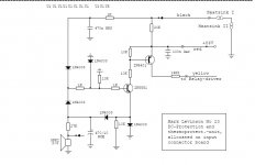
This is the circuit that permanently switches of your amp.
The base of the 2N5551 is connected to a 1k resistor, that is again connected to a 10K resistor.
Short circuit this 10K resistor and your amp won't switch of anymore.
Hans
This is the circuit that permanently switches of your amp.
The base of the 2N5551 is connected to a 1k resistor, that is again connected to a 10K resistor.
Short circuit this 10K resistor and your amp won't switch of anymore.
Hans
Attachments

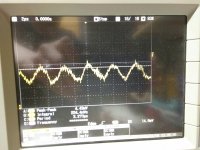
Looking at your scope signal, this can’t be the reason for switching off.
When the DC protection is on the OL-2 board, it can’t be the reason either for switching off because this board is not connected as you said.
The only remaining reason can be a heat sensor that interrupts the power on state.
So is there something getting very hot ??
That brings me back to the question, what happens when reducing with the pot the voltage over the lamps to 25Volt.
Does the amp stays on then ?
Hans
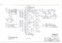
And here is the OL-2 board in total, including your schematic.
I would love to short that resistor but it is in difficult place, might need to take the board off. Need to think.
The complete OL-2 board is disconnected, right ?
But I see connection points going to “thermal” and another to “opto coupler”.
Can you show the missing circuit diagrams where those two signals are coming from.
Hans
In your posting #2 with the complete circuit diagram, I found two thermal switches on the bottom, TS1 and TS2.
They are only connected to the OL-2 board.
So this board must still be connected to these switches and to the “opto coupler” line.
I guess that you only disconnected the 4 connections to “master emitter” and “drive” but that the other connections ate still there, correct ?
So it seems that one of the two thermal switches is activating the “opto coupler” line causing the amp to switch off.
Where are those two thermal switches located and what is causing so much heat that they activate the opto coupler line ??
Hans
Last edited:
To confirm what I said about the thermal switches, you just have to connect 211 to gnd or unplug 209 from the OL-2 board and the amp will no longer switch off.
But that doesn’t solve the question why the thermal switch gets activated in the first place, that has still to be found.
Hans
But that doesn’t solve the question why the thermal switch gets activated in the first place, that has still to be found.
Hans
There are two temperature sensors connected to the heatsinks. One in the positive side heatsink and one for the negative side heatsink. From the temperature sensors there are two wires connected to the main board(which I have soldered). If I disconnect one of those and see if the amp stays on? If not then the other. Like that I could see if the problem is in the negative or positive side.(If the problem is related to the heating.) I did not notice heating though.
Maybe temperature sensor(s) are broken?
Maybe temperature sensor(s) are broken?
I do not think heating is issue. Heatsinks are cold or very slightly warm when switching off. OL-2 board is disconnected.
There are two temperature sensors connected to the heatsinks. One in the positive side heatsink and one for the negative side heatsink. From the temperature sensors there are two wires connected to the main board(which I have soldered). If I disconnect one of those and see if the amp stays on? If not then the other. Like that I could see if the problem is in the negative or positive side.(If the problem is related to the heating.) I did not notice heating though.
Maybe temperature sensor(s) are broken?
Ok. I've got it.
In the mains line there are two switches that are relay activated.
K300 is the switch that is used to switch the Amp on and keep it on.
SW300 is the second relay, and this one can switch the Amp off when acitivated by the optocouples that triggers a triac below the relay.
So the most obvious reason that the amp switches off:
It become a signal to the optocoupler from Board OL-2 caused by a thermal sensor.
This can be checked by disconnecting P332 and P333, first one and then the other.
So when nothing is getting hot, we first have to solve this switch off problem.
Hans
I do not think heating is issue. Heatsinks are cold or very slightly warm when switching off. OL-2 board is disconnected.
What exactly do you mean with OL-2 board is disconnected. Probably only the 4 signals "Master Emitter" and "Drive" ?
But it is still connected to +Vcc Unreg, to the Thermal sensors and to the Optocoupler, right ?
Hans
OK. This is getting more and more interesting. I disconnected the P332 and Now it seems that amp stays on. : ) That was easy because there is removable connector for that.
Does it mean that the opto-coupler is broken? I located that too. Or something in the OL-2?
Does it mean that the opto-coupler is broken? I located that too. Or something in the OL-2?
There is no connections at all from OL-2 to main board.
That's very weird, but we will find it.
The only way the Amp can be switched off is through the optocoupler connection.
When OL-2 is completely disconnected from the right amp, it implies that your other channel is generating this optocoupler signal.
Can you disconnect the +Vcc unreg and the -Vcc unreg from your left amp ?
Maybe its getting too hot because the heatsink is lying horizontally and cannot get cooled by air convection.
Hans
Vcc unregs in the left channel have been disconnected for a while. That cannot be reason for switch off.
Btw. did you see my #116 post.
Btw. did you see my #116 post.
Vcc unregs in the left channel have been disconnected for a while. That cannot be reason for switch off.
Btw. did you see my #116 post.
No I missed posting #116, sorry.
So you disconnected 332 and the amp stays on.
That is very strange because according to the circuit diagram this point is only connected to OL-2, the board that is supposed to be completely disconnected ???
But lets go back to measuring your amp and solve the switch off problem later.
We were at a point where voltage drop on the lamps was ca. 50 Volt, but no current was flowing into R44 and R20 and Vout was near 0 Volt, is this still the current situation ?
So my question is again to measure the voltage on all twelve 0.22R emitter resistors.
Hans
Last edited:
- Home
- Amplifiers
- Solid State
- Mark Levinson No23 repair help