Restore the whole amp back to its original state on the heat sink, of course after having rechecked again all transistors that you mount on that heat sink.
It is much better to do fault finding on a complete amp, because you can measure all important voltages and draw conclusions from there.
So far everything that you measured was intact, so I blame a bad contact for your original problem.
That would have been easy to find with a complete intact amp.
So when all transistors are o.k., mount the whole lot and start with R124 in a safe position when applying power.
Hans
And now there is steady 600mV over R50.
To avoid any misunderstandings, what exactly do you have now, everything mounted on the heatsink ??
Hans
At the moment only Q23, 25, 27 and 26 are mounted in the heatsink and every one has own small heatsink.
At the moment only Q23, 25, 27 and 26 are mounted in the heatsink and every one has own small heatsink.
Sorry, I don't get it.
What's different to the situation before.
Are the two TO3's still connected but without heatsink ?
If so, what is the output voltage now?
Hans
A picture might help
No difference to the situation before. Like in the photos. Sorry but I forget to measure the output voltage. 600mV over the R50. Now I have disconnected all the transistors going to the big heatsink and I am preparing to solder the them with the big heatsink. I will do it tomorrow at my work because there is desoldering station which is very useful in this work.
If I solder tomorrow the the rest of the amp, is the 600mV over R50 safe value to start with(when only one pair of output transistor connected without heatsink)?
If I solder tomorrow the the rest of the amp, is the 600mV over R50 safe value to start with(when only one pair of output transistor connected without heatsink)?
Yes, 600mV is a perfectly safe voltage for one complementary pair without heatsink.
Output voltage should nevertheless be within 25mV with this super low idle current.
I'm impressed by your achievements so far.
Hans

Wow. I admit to being surprised you have been able to keep the amp stable enough with so many things disconnected. Sounds like you are making more progress - great!
And I am also impressed about the knowledge of Hans. You always have the next step waiting for. I am really waiting for tomorrow.
Again, So I think I am having a short somewhere in the ouput stage. If I power up the the board I hear some hum from the amp. Also the unreg voltage drops to somewhere 78V. I turned it quickly off. Without VCCunreg amp seems to work ok. For example the predriver is ok. Also Heatsinks were a bit warm.
How can I start checking where is the problem? Can I just disconnect some of the output transistors? Pairs of course. I have one suspect because the PCB was a bit ripped and I am not sure if the pin is really soldered from the other side of the board.
How can I start checking where is the problem? Can I just disconnect some of the output transistors? Pairs of course. I have one suspect because the PCB was a bit ripped and I am not sure if the pin is really soldered from the other side of the board.
Short WH.1 with WH.5. and tell me if there is still a large amount of current flowing and if not what is Vout ?
Hans
Hans
And in case there is still a lot of current flowing with WH.1 and WH.5 shorted, insert two 40Watt 230V lamps. One in the +Unreg and one in the -Unreg line.
This will limit the current so you can measure the voltages on several critical points without the risk of burning components.
Hans
This will limit the current so you can measure the voltages on several critical points without the risk of burning components.
Hans
How about the 'f'? Should it also be connected to WH.s?
No, that comes later.
Hans
I have shorted WH.1 and WH.5. I have also put the lamp between unregs. The current between WH.s is now 1.1mA.
Handel
Handel
I have shorted WH.1 and WH.5. I have also put the lamp between unregs. The current between WH.s is now 1.1mA.
Handel
1) That you have inserted lamps can only mean that with WH.1 and WH.5 shorted you still had a large current flowing, right ?
That sounds very alarming, but I'm sure we will get it right at the end.
2) You mentioned that only 1.1mA is flowing from WH.1 to WH.5.
Without knowing the voltage at the WH's that doesn't tell very much.
So with the lamps still in place and WH.1 and WH.5 still shorted,
what are the following voltages:
1) On both sides of both lamps, so 4 voltages
2) +Vcc reg and -VCC reg
3) Voltage on WH.1/WH.5
Hans
Sorry Hans, I was not clear enough. I have only one lamp that I have connected between + and - unregs, like before. Then I shorted the The WH.s and measured the current.
Should I measure first the current and voltages in WH.s without the lamp?
I still need to get the second lamp somewhere. Good to hear that you have positive feeling. I am a bit nervous because the soldering is now quite limited.
Should I measure first the current and voltages in WH.s without the lamp?
I still need to get the second lamp somewhere. Good to hear that you have positive feeling. I am a bit nervous because the soldering is now quite limited.
Sorry Hans, I was not clear enough. I have only one lamp that I have connected between + and - unregs, like before. Then I shorted the The WH.s and measured the current.
Should I measure first the current and voltages in WH.s without the lamp?
I still need to get the second lamp somewhere. Good to hear that you have positive feeling. I am a bit nervous because the soldering is now quite limited.
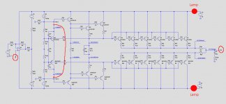
What should have been done with the two lamps is to insert them in resp the +unreg and the -unreg supply.
See image below.
20Watt lamps are also O.K..
Hans
Attachments
- Home
- Amplifiers
- Solid State
- Mark Levinson No23 repair help