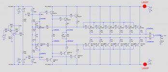
What should have been done with the two lamps is to insert them in resp the +unreg and the -unreg supply.
See image below.
20Watt lamps are also O.K..
Hans
After having inserted the lamps measure the 7 voltages as specified.
Try nothing without the lamps, they are your protection.
Hans
1) That you have inserted lamps can only mean that with WH.1 and WH.5 shorted you still had a large current flowing, right ?
That sounds very alarming, but I'm sure we will get it right at the end.
2) You mentioned that only 1.1mA is flowing from WH.1 to WH.5.
Without knowing the voltage at the WH's that doesn't tell very much.
So with the lamps still in place and WH.1 and WH.5 still shorted,
what are the following voltages:
1) On both sides of both lamps, so 4 voltages
2) +Vcc reg and -VCC reg
3) Voltage on WH.1/WH.5
Hans
I have now added two 40w lamps; one between the common ground and +Vcc unreg and one between common ground and -Vcc unreg.
Here are the results:
+Vcc 86V
-Vcc -86V
WH.1 +0.6V
WH.5 +0.6V
Current between WH.s 1 mA
I don't understand how can I measure four voltages? in respect to what?
I needed to be quick with the measurements because amp turns off itself after a minute or so...
Sorry, that's not what I asked.I have now added two 40w lamps; one between the common ground and +Vcc unreg and one between common ground and -Vcc unreg.
Here are the results:
+Vcc 86V
-Vcc -86V
WH.1 +0.6V
WH.5 +0.6V
Current between WH.s 1 mA
I don't understand how can I measure four voltages? in respect to what?
I needed to be quick with the measurements because amp turns off itself after a minute or so...
Look at the image that I sent you in posting #80.
The lamps should be placed in the supply lines in series with the amp , not parallel to the amp.
Hans
Ok. I will do the changes and do the measurements again.
In the meantime I think I have found the route cause of the problem. You can see it in the attached photo. There is two output transistors on the positive side and two on the negative side that cross the VCCunreg line(thick metal plate) and the lines go under the PCB. For some reason many of them are not connected. I am just wondering why? It might be that the hole is two big and the tin does not solder the pin to the line. In the other channel they are clearly connected.
The question is now, should I remove those four transistors and try to see if it can be soldered better or should I just solder new wires on top?
Handel
Attachments

I would say, just do nothing until the lamps are mounted.Ok. I will do the changes and do the measurements again.
In the meantime I think I have found the route cause of the problem. You can see it in the attached photo. There is two output transistors on the positive side and two on the negative side that cross the VCCunreg line(thick metal plate) and the lines go under the PCB. For some reason many of them are not connected. I am just wondering why? It might be that the hole is two big and the tin does not solder the pin to the line. In the other channel they are clearly connected.
The question is now, should I remove those four transistors and try to see if it can be soldered better or should I just solder new wires on top?
Handel
There are two reasons why these solderings are looking bad
1) Because of insufficient heat of the soldering iron when soldering, or
2) Because there was so much current flowing that because of the generated heat these points unsoldered themself.
When looking at the image below, this point really seems burnt.
Hans
Attachments
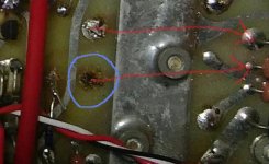
Exactly that point started my suspicions. When I installed that specific transistor the pad dropped. The age starts to show...
Now I have reinstalled the lamps in the right way ; )
Now I have reinstalled the lamps in the right way ; )
So, now I have installed two lamps in SERIES to the Vcc unregs. I also soldered jumper wires for the four transistors that had the connection issue. WH.s are now shorted. First voltage is the power supply side, second on the board side.
+87/+86.5
-87.3/-86.5
Voltages in WH.1 and WH.5 are 0.7/0.7
I am happy that the amp stays on now.
Handel
+87/+86.5
-87.3/-86.5
Voltages in WH.1 and WH.5 are 0.7/0.7
I am happy that the amp stays on now.
Handel
O.K. That's a big step forward.
A cold 40 Watt lamp has roughly a resistance of 100 Ohm, so 0.5 Volt across means only 5 mA, completely harmless and no reason for the amp to switch off, so I suspect the amp was oscillating.
Now we have the following steps to perform.
1)You measured 0.7 Volt with WH.1 and WH.5 connected together, but without the additional connection to 'f' , right ?
This is too far off and indicates a problem.
Now with WH.1 and WH.5 still connected
2) What is Vout, or 'f', this should be within 50mV.
3) What are +Vcc Reg and -Vcc Reg. If ca +/- 84 Volt, its O.k.
4) disconnect WH.1 from WH.5 and measure the current between them with your multimeter, should be ca 16 mA.
With WH.1 and WH.5 now disconnected
5) what happens to the voltages over the lamps,
6) to Vout,
7) and to the voltage over R50
8) and to the voltages on resp. WH.1 and WH.5
This is it for the moment.
Depending on the outcome of all these questions, we will go on.
Success.
Hans
Last edited:
That is good to hear.
I measured the Vout or 'f' and that is 11.5mV. Vcc unregs were + and - 86V. After disconnecting WH.s the current between was 17mA, but again the amp started turning itself off. I still could measure the lamps from positive side, those were 87/84V. I also tried to turn the pot to safer side but it did not help. Last time it helped. Maybe the current increases over the R50 like last time.
I measured the Vout or 'f' and that is 11.5mV. Vcc unregs were + and - 86V. After disconnecting WH.s the current between was 17mA, but again the amp started turning itself off. I still could measure the lamps from positive side, those were 87/84V. I also tried to turn the pot to safer side but it did not help. Last time it helped. Maybe the current increases over the R50 like last time.
Negative Vcc unregs are -87/-85V. Voltage over R50 is 280mV, Vout = 10mV.
WH.1/WH.5 = 1.55V/-1.17V
WH.1/WH.5 = 1.55V/-1.17V
Most of it is good news.
It seems that your pre-drivers and everything before are still working properly.
But WH.1 and WH.5 not connected, current through the lamps is only some 30mA, and that's no reason for the amp to switch off.
So again my suspicion is that your Complementary pairs are oscillating.
That's why we will increase the idle current.
Don't worry, the lamps will prevent an accident from happening.
Turn the pot to a value where you have between 1.1 and 1.2 Volt on R50 and tell me the voltage drop over the lamps.
Hans
I turned the pot so that I have 1.1V over the R50. Now the voltage drops are HUGE: 51/52V.
What does the oscillating mean really? Can I measure it from the with the scope if that is the case?
Handel
What does the oscillating mean really? Can I measure it from the with the scope if that is the case?
Handel
I turned the pot so that I have 1.1V over the R50. Now the voltage drops are HUGE: 51/52V.
What does the oscillating mean really? Can I measure it from the with the scope if that is the case?
Handel
That sounds again very good.
50Volt over 100 Ohm is 500mA.
Now measure on R44 or R20, and turn the pot back to 275mA idle current. Each resistor should show now 27.5mV.
What is now Vout and is the amp still switching off after some time ?
When oscillating, you can see this on a scope, must be in the tens of Mhz.
But with this idle current, I suspect no oscillations.
Hans
That's a miracle.
When increasing the voltage over R50 to 1.1Volt, the voltage drop over the lamps is approx 50Volt, indicating some 500mA.
That current can't go anywhere, but only through the complementary output transistors.
That no voltage is on R44 and R20 can only mean that WH.2 and WH.4 are shorted by the OL-2 board.
So disconnect these two points and measure again with the voltage on R50 between 1.0 and 1.1 Volt.
And also tell the Vout voltage.
Hans
- Home
- Amplifiers
- Solid State
- Mark Levinson No23 repair help