An ML 23 AC-2 board is just as perfect for my purpose, which is only getting the exact sizing of all the transfer points.
I would be very happy if you could make such a board available to me.
Hans
I would be very happy if you could make such a board available to me.
Hans
I think I am in favor of having new PCB that I can populate with old components because I have a lot of them. But in that case I will loose the possibility of having the 23.5 updates, they will never fit on the board because it is already full. As Hans already mentioned with new SMD components all would fit easily on one board.
Any other comments views or ideas on this?
BTW. Does somebody have the 23.5 schematic updates? would be interesting to see them.
Any other comments views or ideas on this?
BTW. Does somebody have the 23.5 schematic updates? would be interesting to see them.
Mark Levinson (ML23.5) OPS correction , part one
Since quite a number of ML23 and 23.5 are blowing their Power transistors, I wondered how this could be possible despite the OL-2 protection circuit.
That’s why I spent some time trying to understand this and to find possible causes and remedies.
Because so far all ML amps that I came across have exactly the same protection circuit, results are even more universal and do not apply to the 23 series alone but also to the ML27.x the ML20.x, the ML33.x and probably a lot more models.
That’s why ML23.5 in the headline was put in brackets.
Considerations:
There are two ways to protect your OPS:
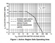
One is to limit the current to certain levels derived from the power transistors SOA.
The other one is a crow bar type that shuts down the current to a low level until its safe again to restore normal operation. The crow bar type is what Mark Levinson has selected.
The first method is less rigorous, but has a rather large transition zone, thereby affecting the amp’s performance earlier as wanted and at the same time the OPS will go on heating as long as the protection circuit has to remain active, possibly resulting in overheating.
One other real problem with inductive loads is the tendency to oscillate when it comes to action because of feedback.
The crowbar comes abrupt into action, has no oscillation problems and prevents the OPS from overheating as long as the unsafe situation remains.
However abrupt current reductions lead to significant voltage peaks with inductive loads. The amp will be well protected, but your speakers won’t like these spikes at all.
So the activation speed has to be tempered, which again may lead to interaction with the switching point as we will see later.
What seems at first sight like a simple problem results in a sort of complicated struggle to get all the worms in the pot.
Simulation setup:
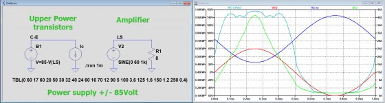
I started to construct a simple reference circuit in LTSice with a conditional voltage source that replicates the voltage on the Power transistors (Supply voltage minus LS voltage), connected to a current source loaded with a table replicating the exact SOA.
The ML23 has 6 output transistors, but to keep some safety margin I multiplied the single SOA current values with a factor 4 to account for individual differences between the transistors.
With the help of this simple add-on I had a direct reference of what was allowed versus the real load.
See first image below showing what is to be expected in current and power limits versus applied voltage.
The exact ML23 current OPS, replicated in a subckt, worked on the encircled Mark Levinson current protection circuit in the second image below, enabling to simulate all possible conditions.
In a paper from Cyril Bateman where he investigated the effect of different LS cables, he used a LS model of 4.8R in series with 150uH being a close match to his real loudspeaker
https://www.google.nl/url?sa=t&rct=...eraction.pdf&usg=AOvVaw3jx40P0yY-_qliylvETm-8
Since I wanted to know the effects of phase shift between voltage and current on the effectiveness of the OPS protection, but also the protection during a short circuit, I planned to use various resistive loads from 0.1R (Short circuit) to 8R at frequencies from 50Hz to 10Khz and inductances from zero to 200uH to find eventual weak spots in the protection circuitry.
Since quite a number of ML23 and 23.5 are blowing their Power transistors, I wondered how this could be possible despite the OL-2 protection circuit.
That’s why I spent some time trying to understand this and to find possible causes and remedies.
Because so far all ML amps that I came across have exactly the same protection circuit, results are even more universal and do not apply to the 23 series alone but also to the ML27.x the ML20.x, the ML33.x and probably a lot more models.
That’s why ML23.5 in the headline was put in brackets.
Considerations:
There are two ways to protect your OPS:
One is to limit the current to certain levels derived from the power transistors SOA.
The other one is a crow bar type that shuts down the current to a low level until its safe again to restore normal operation. The crow bar type is what Mark Levinson has selected.
The first method is less rigorous, but has a rather large transition zone, thereby affecting the amp’s performance earlier as wanted and at the same time the OPS will go on heating as long as the protection circuit has to remain active, possibly resulting in overheating.
One other real problem with inductive loads is the tendency to oscillate when it comes to action because of feedback.
The crowbar comes abrupt into action, has no oscillation problems and prevents the OPS from overheating as long as the unsafe situation remains.
However abrupt current reductions lead to significant voltage peaks with inductive loads. The amp will be well protected, but your speakers won’t like these spikes at all.
So the activation speed has to be tempered, which again may lead to interaction with the switching point as we will see later.
What seems at first sight like a simple problem results in a sort of complicated struggle to get all the worms in the pot.
Simulation setup:
I started to construct a simple reference circuit in LTSice with a conditional voltage source that replicates the voltage on the Power transistors (Supply voltage minus LS voltage), connected to a current source loaded with a table replicating the exact SOA.
The ML23 has 6 output transistors, but to keep some safety margin I multiplied the single SOA current values with a factor 4 to account for individual differences between the transistors.
With the help of this simple add-on I had a direct reference of what was allowed versus the real load.
See first image below showing what is to be expected in current and power limits versus applied voltage.
The exact ML23 current OPS, replicated in a subckt, worked on the encircled Mark Levinson current protection circuit in the second image below, enabling to simulate all possible conditions.
In a paper from Cyril Bateman where he investigated the effect of different LS cables, he used a LS model of 4.8R in series with 150uH being a close match to his real loudspeaker
https://www.google.nl/url?sa=t&rct=...eraction.pdf&usg=AOvVaw3jx40P0yY-_qliylvETm-8
Since I wanted to know the effects of phase shift between voltage and current on the effectiveness of the OPS protection, but also the protection during a short circuit, I planned to use various resistive loads from 0.1R (Short circuit) to 8R at frequencies from 50Hz to 10Khz and inductances from zero to 200uH to find eventual weak spots in the protection circuitry.
Attachments
Mark Levinson (ML23.5) OPS correction, part two
8R load:
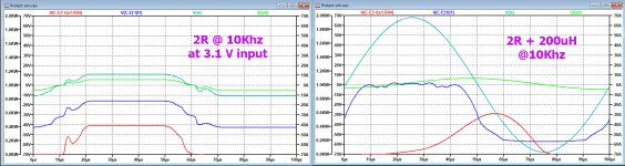
The first image below shows the response for an output voltage of 70Volt-pk with resp. 2nH and 200uH load in series with the 8R load.
What you see are: Output Voltage at the LS (Cyan), Current through the LS (green), Consumed Power in the upper halve of the OPS (red) and Allowed Power consumption according to 4 x SOA (blue).
The lower halve will consume exactly the same amount of power and is not shown for that reason.
With 2nH, the red curve is way below the blue curve, so nothing to fear and also in case of the added 200uH inductance, the red curve comes close to the blue curve but is still O.K.
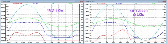
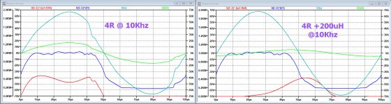
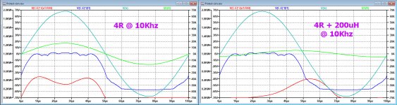
4R load:
Second image below shows the same conditions as above but now for 4R @ 10Khz.
With 2nH, the crowbar is on the brink of coming into action, but this action is aborted resulting nevertheless in a rather distorted signal. But consumed power is well within the allowed curve.
With 200uH, because of the phase shift, less current is now flowing, resulting in no crowbar coming into action.
However, where power consumption with the 8R load was still within the SOA, this is no longer the case and the power consumption exceeds shortly the SOA at this frequency of 10 KHz.
Going down in frequency, the situation relaxes as from 1 KHz and below.
With 2nH the crowbar doesn’t try come into action anymore and with 200uH the consumed power is now within the allowed curve. See third image taken at 1Khz.
Knowing quite well that nobody is listening to an above 1Khz signal at almost 40 Vrms output, realise that I’m just investigating the extremes that can happen because of oscillation or an incorrect level adjustment of the equipment feeding the amp.
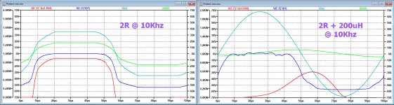
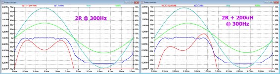
2R load:
As expected the situation with 2R becomes even worse, see 4th image.
With 2nH, the crowbar comes into action, restricting the current to 20Amp. However the red curve lays way above the allowed blue curve, so the amp will definitely die!!
With 200uH in series with 2R, the crowbar is not activated, but the red curve goes shortly beyond the blue line, probably still acceptable because of the short duration.
Going down to 300Hz results in the 5th image, where everything now seems fine.
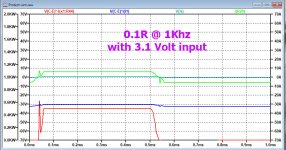
Shortened with 0.1R:
When short circuiting the amp, the resulting effect is visible in the 6th image below.
And although the crow bar has been triggered, it’s obvious that the red curve still lays way above the allowed blue curve and the amp will certainly go down.
So maybe I’m a bit too conservative in multiplying the individual SOA by 4 with six power transistors, but even then the discrepancy between consumed and allowed power consumption would be rather exceeded.
Conclusion so far:
The current limit circuitry is not in all cases effectively preventing the amp from going into destruction and even when the crowbar comes into action, the consumed power lays in several cases way above the SOA.
The other thing is that the protection circuit is strongly dependant on frequency.
Were the output signal is still unaffected at lower frequencies, it comes partly into action at higher frequencies, resulting in noticeable distorted signals as for 10Khz 4R in the second image.
.
8R load:
The first image below shows the response for an output voltage of 70Volt-pk with resp. 2nH and 200uH load in series with the 8R load.
What you see are: Output Voltage at the LS (Cyan), Current through the LS (green), Consumed Power in the upper halve of the OPS (red) and Allowed Power consumption according to 4 x SOA (blue).
The lower halve will consume exactly the same amount of power and is not shown for that reason.
With 2nH, the red curve is way below the blue curve, so nothing to fear and also in case of the added 200uH inductance, the red curve comes close to the blue curve but is still O.K.
4R load:
Second image below shows the same conditions as above but now for 4R @ 10Khz.
With 2nH, the crowbar is on the brink of coming into action, but this action is aborted resulting nevertheless in a rather distorted signal. But consumed power is well within the allowed curve.
With 200uH, because of the phase shift, less current is now flowing, resulting in no crowbar coming into action.
However, where power consumption with the 8R load was still within the SOA, this is no longer the case and the power consumption exceeds shortly the SOA at this frequency of 10 KHz.
Going down in frequency, the situation relaxes as from 1 KHz and below.
With 2nH the crowbar doesn’t try come into action anymore and with 200uH the consumed power is now within the allowed curve. See third image taken at 1Khz.
Knowing quite well that nobody is listening to an above 1Khz signal at almost 40 Vrms output, realise that I’m just investigating the extremes that can happen because of oscillation or an incorrect level adjustment of the equipment feeding the amp.
2R load:
As expected the situation with 2R becomes even worse, see 4th image.
With 2nH, the crowbar comes into action, restricting the current to 20Amp. However the red curve lays way above the allowed blue curve, so the amp will definitely die!!
With 200uH in series with 2R, the crowbar is not activated, but the red curve goes shortly beyond the blue line, probably still acceptable because of the short duration.
Going down to 300Hz results in the 5th image, where everything now seems fine.
Shortened with 0.1R:
When short circuiting the amp, the resulting effect is visible in the 6th image below.
And although the crow bar has been triggered, it’s obvious that the red curve still lays way above the allowed blue curve and the amp will certainly go down.
So maybe I’m a bit too conservative in multiplying the individual SOA by 4 with six power transistors, but even then the discrepancy between consumed and allowed power consumption would be rather exceeded.
Conclusion so far:
The current limit circuitry is not in all cases effectively preventing the amp from going into destruction and even when the crowbar comes into action, the consumed power lays in several cases way above the SOA.
The other thing is that the protection circuit is strongly dependant on frequency.
Were the output signal is still unaffected at lower frequencies, it comes partly into action at higher frequencies, resulting in noticeable distorted signals as for 10Khz 4R in the second image.
.
Attachments


Mark Levinson (ML23.5) OPS correction, part three
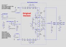
Armed with the above results, the next step was trying to find possible ways of improving the protection circuit’s effectiveness.
When shortening the amp, the crow bar limits the current to 20 Amps which is way too much.
This current is caused by 20R + the six diodes in series with the crowbar. The crowbar is constructed with two transistors, acting as a thyristor.
The activated “thyristor” in series with these 6 diodes + 20R measures when activated a total voltage drop of 4.75 Volt between VAS and Emitter.
This results independently from the LS load in 20 Amp through the OPS of which 20A*0.22R/6= 0.73 Volt is taken by the six 0.22R emitter resistors and the 20A*0.1R= 2 Volt by the following 0.1 R resistor.
So it’s quite easy to bring this down to within SOA levels by taking out 4 of the six diodes. This results in a current limit of 6A, now well within the SOA.
That was easy to achieve, but what effect does this have on the other properties ?
I won’t go into details, but also changing the trigger point to a lower level, made the 470uF + 33.2R obsolete, and restricting the distortion of signals at higher frequencies could be cured by reducing the 10K thyristor trigger resistor to 600R.
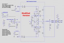
Circuit with all the changes is now in the first figure below together with the original version to compare as the second image.
Doing all the same test as before with the original circuit, results in the rest of the images.
8R Load:
This version works just perfectly safe as before and won’t be shown again.
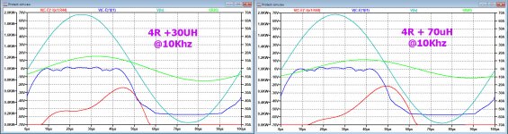
4R load:
At 10Khz, performance is now completely unaffected by the crowbar, leaving the signal perfectly intact, where before a strong distortion was noticeable.
With 200uH, the consumed power is still shortly beyond the SOA as before, see the third image.
One might think that 200uF is a bit over the top, but with 70uH the exceedance over the SOA line is even larger and only below 30uH is everything within boundaries, see image no. 4.
With the available protection circuit, it was not possible to restrict this without hurting other areas, but hopefully it won’t result in a problem because duration of this anomaly is a very short 10 usec and with lower frequencies it rapidly comes within safe area.
And as from 1 Khz and below all power curves with 200uH are well within the SOA.
2R Load:
As before, with a pure resistive load, at 10Khz the crowbar comes into action but while limiting the current now to 6A instead of the previous 20A, everything seems well under control to prevent any damage.
With 200uH, because of the lower current drawn, results in a perfect signal reproduction, see image no.5.
At this 10Khz, output signal has to be reduced from 49 Vrms to 30 Vrms to prevent the crowbar coming into action.
However as from 3.5 Khz and below, full power can be applied.
With 300Hz without and with 200uH, everything is within safe margins, see image 6.
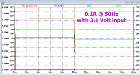
0.1R Load:
Crowbar is triggered but unlike before, power consumption is now perfectly under the SOA . Image 7.
Conclusion:
With the applied changes, short circuiting the amp is now perfectly safe and distortion of the signal at higher frequencies is completely avoided.
Exceeding the SOA with inductive loads only happens at high output/high frequencies and seems rather harmless because of the short duration, although no figures are available in the specification.
The SOA graph shown in part one applies for a temp of 200 C max, so there is probably some margin available for shortly exceeding the SOA at 10Khz.
I would say that protection went from inadequate to quite well.
Hans
Armed with the above results, the next step was trying to find possible ways of improving the protection circuit’s effectiveness.
When shortening the amp, the crow bar limits the current to 20 Amps which is way too much.
This current is caused by 20R + the six diodes in series with the crowbar. The crowbar is constructed with two transistors, acting as a thyristor.
The activated “thyristor” in series with these 6 diodes + 20R measures when activated a total voltage drop of 4.75 Volt between VAS and Emitter.
This results independently from the LS load in 20 Amp through the OPS of which 20A*0.22R/6= 0.73 Volt is taken by the six 0.22R emitter resistors and the 20A*0.1R= 2 Volt by the following 0.1 R resistor.
So it’s quite easy to bring this down to within SOA levels by taking out 4 of the six diodes. This results in a current limit of 6A, now well within the SOA.
That was easy to achieve, but what effect does this have on the other properties ?
I won’t go into details, but also changing the trigger point to a lower level, made the 470uF + 33.2R obsolete, and restricting the distortion of signals at higher frequencies could be cured by reducing the 10K thyristor trigger resistor to 600R.
Circuit with all the changes is now in the first figure below together with the original version to compare as the second image.
Doing all the same test as before with the original circuit, results in the rest of the images.
8R Load:
This version works just perfectly safe as before and won’t be shown again.
4R load:
At 10Khz, performance is now completely unaffected by the crowbar, leaving the signal perfectly intact, where before a strong distortion was noticeable.
With 200uH, the consumed power is still shortly beyond the SOA as before, see the third image.
One might think that 200uF is a bit over the top, but with 70uH the exceedance over the SOA line is even larger and only below 30uH is everything within boundaries, see image no. 4.
With the available protection circuit, it was not possible to restrict this without hurting other areas, but hopefully it won’t result in a problem because duration of this anomaly is a very short 10 usec and with lower frequencies it rapidly comes within safe area.
And as from 1 Khz and below all power curves with 200uH are well within the SOA.
2R Load:
As before, with a pure resistive load, at 10Khz the crowbar comes into action but while limiting the current now to 6A instead of the previous 20A, everything seems well under control to prevent any damage.
With 200uH, because of the lower current drawn, results in a perfect signal reproduction, see image no.5.
At this 10Khz, output signal has to be reduced from 49 Vrms to 30 Vrms to prevent the crowbar coming into action.
However as from 3.5 Khz and below, full power can be applied.
With 300Hz without and with 200uH, everything is within safe margins, see image 6.
0.1R Load:
Crowbar is triggered but unlike before, power consumption is now perfectly under the SOA . Image 7.
Conclusion:
With the applied changes, short circuiting the amp is now perfectly safe and distortion of the signal at higher frequencies is completely avoided.
Exceeding the SOA with inductive loads only happens at high output/high frequencies and seems rather harmless because of the short duration, although no figures are available in the specification.
The SOA graph shown in part one applies for a temp of 200 C max, so there is probably some margin available for shortly exceeding the SOA at 10Khz.
I would say that protection went from inadequate to quite well.
Hans
Attachments


I mentioned OPS Correction in the headings of the above postings.
This should of course be OPS Protection
Hans
This should of course be OPS Protection
Hans
Hello Hans,
Thank you very much for the very comprehensive study for the protection circuit. As soon as I have time I will make the modifications for my OL-2 boards.
Thank you very much for the very comprehensive study for the protection circuit. As soon as I have time I will make the modifications for my OL-2 boards.
Hans there is a paper from Mark Levinson-Madrigal-Bryston and now days owned by Samsung how to change the protection circuit to work as it should. I consider this protection obsolete, not stable, adds distortion(microcurrents start at ~400mV Vbe @ 25*C). Better protection you may find on most receivers, NAD amps etc. with a single transistor-sensor-comparator. There are many other problems with 23.5, 27 - overheating transistors, electrolytic and foil caps near power resistors, zeners current is on edge - all do self inflicted damage. Smd is not recommended most of resistors are high power mil grade
Hi Roumen,
Your analysis of the 23.5 is rather negative, don’t you agree ?
I would be most interested in the paper you mention, although I still don’t get what ML has to do with Bryston and Samsung.
And yes, the OPS protection is not optimal as shown in my analysis, so simply consider the amp as unprotected.
But it’s not to be surprised that an almost 40 years old amp is needing some TLC, mainly caps and PCB problems, but I’m not aware of overheating transistors or problems with foil caps or any other of the problems you describe.
Where did you get this information ?
Looking forward to get more info on the paper you mentioned.
Hans
I have searched for this paper using a variety of search word permutations, but can't find it, or any connection between Levinson and either Bryston or Samsung. Please provide a link, or better, the paper so we can all better understand your thoughts on this.
Brilliant improvement to the protection circuit
Hans, that's excellent analysis and redesign. Much respect.
Hans, that's excellent analysis and redesign. Much respect.
Mark Levinson (ML23.5) OPS correction, part three
Armed with the above results, the next step was trying to find possible ways of improving the protection circuit’s effectiveness.
When shortening the amp, the crow bar limits the current to 20 Amps which is way too much.
This current is caused by 20R + the six diodes in series with the crowbar. The crowbar is constructed with two transistors, acting as a thyristor.
The activated “thyristor” in series with these 6 diodes + 20R measures when activated a total voltage drop of 4.75 Volt between VAS and Emitter.
This results independently from the LS load in 20 Amp through the OPS of which 20A*0.22R/6= 0.73 Volt is taken by the six 0.22R emitter resistors and the 20A*0.1R= 2 Volt by the following 0.1 R resistor.
So it’s quite easy to bring this down to within SOA levels by taking out 4 of the six diodes. This results in a current limit of 6A, now well within the SOA.
That was easy to achieve, but what effect does this have on the other properties ?
I won’t go into details, but also changing the trigger point to a lower level, made the 470uF + 33.2R obsolete, and restricting the distortion of signals at higher frequencies could be cured by reducing the 10K thyristor trigger resistor to 600R.
Circuit with all the changes is now in the first figure below together with the original version to compare as the second image.
Doing all the same test as before with the original circuit, results in the rest of the images.
8R Load:
This version works just perfectly safe as before and won’t be shown again.
4R load:
At 10Khz, performance is now completely unaffected by the crowbar, leaving the signal perfectly intact, where before a strong distortion was noticeable.
With 200uH, the consumed power is still shortly beyond the SOA as before, see the third image.
One might think that 200uF is a bit over the top, but with 70uH the exceedance over the SOA line is even larger and only below 30uH is everything within boundaries, see image no. 4.
With the available protection circuit, it was not possible to restrict this without hurting other areas, but hopefully it won’t result in a problem because duration of this anomaly is a very short 10 usec and with lower frequencies it rapidly comes within safe area.
And as from 1 Khz and below all power curves with 200uH are well within the SOA.
2R Load:
As before, with a pure resistive load, at 10Khz the crowbar comes into action but while limiting the current now to 6A instead of the previous 20A, everything seems well under control to prevent any damage.
With 200uH, because of the lower current drawn, results in a perfect signal reproduction, see image no.5.
At this 10Khz, output signal has to be reduced from 49 Vrms to 30 Vrms to prevent the crowbar coming into action.
However as from 3.5 Khz and below, full power can be applied.
With 300Hz without and with 200uH, everything is within safe margins, see image 6.
0.1R Load:
Crowbar is triggered but unlike before, power consumption is now perfectly under the SOA . Image 7.
Conclusion:
With the applied changes, short circuiting the amp is now perfectly safe and distortion of the signal at higher frequencies is completely avoided.
Exceeding the SOA with inductive loads only happens at high output/high frequencies and seems rather harmless because of the short duration, although no figures are available in the specification.
The SOA graph shown in part one applies for a temp of 200 C max, so there is probably some margin available for shortly exceeding the SOA at 10Khz.
I would say that protection went from inadequate to quite well.
Hans
I have searched for this paper using a variety of search word permutations, but can't find it, or any connection between Levinson and either Bryston or Samsung. Please provide a link, or better, the paper so we can all better understand your thoughts on this.
I’m afraid that the existance of a paper was based on hear say info instead of substance.
Or was it meant as joke to upset ML owners ?
Hans
I think I have the worlds first ML23 amp which has the protection circuit working as it was meant to be. 😀😀 Thank you Hans!
I could do all the modifications for the OL-2 boards without removing it from the chassis which was much less work than I expected.
I would like to do some tests to check if the protection works but it sounds scary! I fully trust for the expertise of Hans though, but I might have made errors in soldering. So short circuiting the speaker terminals is one test, another adding enough input signal level but then I need right type of resistor connected to speaker terminals?
Is there more tests I can do?
Btw. The closest value that I found for the R4 and R13 was 604 ohm. I hope it does not make any change for the operation.
Hi Hannu,
Happy new year and congrats with the mods, and yes the 604 is perfectly O.K.
You could connect your multimeter in the high AC amp position (20A?) to the LS terminals while using a frequency below 1Khz that is still supported by your multi meter.
When turning up the level from zero, you should see that the meter stops going up somewhere around 6Amp.
At that moment the amp is consuming 600Watt, so after some time the thermal protection may switch off the amp.
Hans
Last edited:
Hello Hans,
Happy new year you too!
10A is the max range of my multimeter.
How do you know the resistance(impedance in this case) of the multimeter?
Can you explain how you get those values?
Happy new year you too!
10A is the max range of my multimeter.
How do you know the resistance(impedance in this case) of the multimeter?
Can you explain how you get those values?
What is the most sensitive voltage range of your multimeter ?
Let’s say it is 100mV full scale.
Then your 10A range has a resistance of 100mV/10A= 10mOhm.
Hans
Let’s say it is 100mV full scale.
Then your 10A range has a resistance of 100mV/10A= 10mOhm.
Hans
If my amp pushes 600W power, it means from P =R*I^2 that current is 7,7A. Protection circuit comes to play at 6A?
Does this protection circuit only limit the current and not switch the amp off?
Only temperature sensor can switch the amp off?
Does this mean that when listening music at high volume I do not know when the protection circuit comes to play?
Does this protection circuit only limit the current and not switch the amp off?
Only temperature sensor can switch the amp off?
Does this mean that when listening music at high volume I do not know when the protection circuit comes to play?
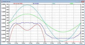
The current limit depends on the voltage on the OPS, thereby following the manufacturers SOA (Safe Operating Area)
With zero volt at the output, there is 86Volt on the OPS transistors and only 6 Amps are allowed, generating 6A x 86V= 516Watt in your OPS while supplying 6A x zero Ohm = zero watt to the load !
See the first image below where the red line, the real consumed power, does not exceed the blue line which is the maximum allowable power according to the SOA with a current limited to 6 Amp.
The higher the output voltage, the lower the voltage on your OPS and the higher the current limit becomes.
With 600Watt into a 2R load, current is 17.3Amp rms or 24.5Amp peak at 49Volt peak.
At that moment the voltage on the OPS is much lower at 86-49=37Volt.
Now look at the second image below that is for 800Watt into 2R and you will see that even 35Amps current (green line) will be supplied without any problem.
Again the red line never exceeds the blue line, so everything is well under control.
So the specified figures by ML of 200Watt into 8R up to 800Watt into 2R are fully supported by the output protection as shown in all the supplied images in the previous postings..
But added to that is now a short circuit protection that is within the SOA and the prevention of signal distortion at high level high frequencies that happens with the ML protection.
And to your last question: yes the amp only switches off 1) when getting overheated OR 2) when DC offset more than +/-0.6Volt is detected at the LS output.
Hans
.
Attachments
Thanks a lot for the explanation, Hans. I am slowly starting to understand this.
What I still do not understand is that why in the second image above in the moment when the voltage and the current in LS are in peak, the power consumption is lower than when voltage and current is rising or falling?
Is the voltage in the OPS lower and that is why the power consumption is lower?
Is the voltage in the OPS same as +VCC unreg?
BTW. what OPS stands for?
- Home
- Amplifiers
- Solid State
- Mark Levinson No23 repair help