Before you take things apart, which is indeed very inconvenient, I strongly advise to first replace the two 680uF caps on the upper board and to make Vreg+ equal to Vreg-.
When these two voltages are not equal in magnitude, the start up circuit interferes with the signal chain, that's why.
Hans
I did say that the regulated voltages have to be of exact the same magnitude for each channel, not at all the currents of both channels.
What do you mean with “there is no start mode ....” ?
What model do you have to 27 or 27.5 ?
Hans
Previously, when you turn on the amplifier in the first second, my speakers moved on the speakers.
As I learned this is a soft start mode due to the absence of a relay in the circuit. So after replacing the worn parts, 27.5 turns on, but this soft start mode is not. The amplifier works, but there is no sound.
So in fact the amp does not work because you get no sound.
At what point did you measure those 4 voltages ?
What are the voltages of P6 and P7 with respect to gnd and what current flows when connecting your multimeter set in the DC current mode directly between P6 and P7 ?
Hans
At what point did you measure those 4 voltages ?
What are the voltages of P6 and P7 with respect to gnd and what current flows when connecting your multimeter set in the DC current mode directly between P6 and P7 ?
Hans
Hans, I measured these four voltages for about 10 minutes of the amplifier's operation.
It was possible to measure napryadenie p6-earth p7-earth
One channel 0.71 0.68 the second channel 0.7 0.68.
Between p6 p7 could not measure, I can not crawl, tomorrow I will try to measure
It was possible to measure napryadenie p6-earth p7-earth
One channel 0.71 0.68 the second channel 0.7 0.68.
Between p6 p7 could not measure, I can not crawl, tomorrow I will try to measure
The voltages on P6 and P7 are telling that your soft start circuit stays locked in the soft start state and does not release P6 and P7 which should become resp +1.9 and -1.9Volt after the soft start has ended.
Hans
Hans
The voltages on P6 and P7 are telling that your soft start circuit stays locked in the soft start state and does not release P6 and P7 which should become resp +1.9 and -1.9Volt after the soft start has ended.
Hans
What do you think might interfere with unlocking the soft start? What should I check?
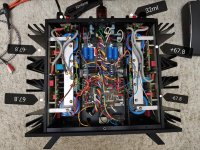
It will be close to impossible to measure anything unless you remove the top board.
It is Q216 that's doing the soft start, and either this mosfet is broken, or the cap C213 on it's gate is shorted or something in that range.
C213 should be slowly charged positive after powering up, thereby letting the mosfet transfer from an open into a low ohmic position, thereby releasing P6 and P7.
Hans
...P6 and P7 which should become resp +1.9 and -1.9Volt after the soft start has ended...
Interesting. P6 P7 are 1,76 / 1,73 in my amp.
Still waiting for the 680uF 100V (Nippon LXV were on offer). I took out C21, C22, they seem to measure ok, but will still replace them. If ripple is still there afterwards, will check C23 C25 .. and 1900uF, just to be sure, before I start taking boards apart.
BR
PS: "..mosfet transfer from an open into a low ohmic position.." so, if it closes not fully, it drains partial current from the driveline?
Last edited:
Those voltages depend a bit on the Bias current and on Vbe variations, but it clearly is outside the ca. 0.7V at soft start.
Hans
Hans
It will be close to impossible to measure anything unless you remove the top board.
It is Q216 that's doing the soft start, and either this mosfet is broken, or the cap C213 on it's gate is shorted or something in that range.
C213 should be slowly charged positive after powering up, thereby letting the mosfet transfer from an open into a low ohmic position, thereby releasing P6 and P7.
Hans
Hans, thank you very much for the information! Will the channel work without a higher fee? Or will I have to increase the space by extending the jumpers(wires)?
Interesting. P6 P7 are 1,76 / 1,73 in my amp.
Still waiting for the 680uF 100V (Nippon LXV were on offer). I took out C21, C22, they seem to measure ok, but will still replace them. If ripple is still there afterwards, will check C23 C25 .. and 1900uF, just to be sure, before I start taking boards apart.
BR
PS: "..mosfet transfer from an open into a low ohmic position.." so, if it closes not fully, it drains partial current from the driveline?
Prior to repair I learned in Harman at the expense of condensatorul. They did not recommend changing 680uf 75v if they are normal, because they are better in quality than new ones. But you still unsubscribe, which will give you a replacement. They wrote that the hiss most likely comes from the bourns resistors.
In my ml 26 preamp, the channel rustled. After replacing bourns, everything is fine!
Yes, but that’s not very likely to happen."..mosfet transfer from an open into a low ohmic position.." so, if it closes not fully, it drains partial current from the driveline?
A much higher risk of draining current from the driveline is when Vreg+ and Vreg- are not equal in magnitude, because in that case the mosfet can open one of the two transistors with their emitters to gnd.
The result is that the LS output will show a relatively large offset.
As long as that’s not the case, everything is o.k.
Hans
Can you be a bit more explicit, because I honestly don’t understand what you mean.Will the channel work without a higher fee? Or will I have to increase the space by extending the jumpers(wires)?
Hans
Hans, thank you very much for the information! Will the channel work without a higher fee? Or will I have to increase the space by extending the jumpers(wires)?
You wrote that I can't get to Q216 if I don't remove ac 8.5, I ask you, can you turn on the amplifier without the ac8.5 board? Or do I have to increase the space between ac 8 and ac8.5 wires?
They did not recommend changing 680uf 75v if they are normal, because they are better in quality than new ones....They wrote that the hiss most likely comes from the bourns resistors.
Thnx for passing that on. Although C21 seems ok, PosReg does have a ripple problem, and there must be a reason. I'll check.
Yes, resistors can add increased noise if defective.
You did take apart AC-8 and AC-8.5 for your recapping job, correct? Do you remember which ones on AC-8.5 were Bourns-made?
BR
Last edited:
Yes, I remember. I'll write to you later.Thnx for passing that on. Although C21 seems ok, PosReg does have a ripple problem, and there must be a reason. I'll check.
Yes, resistors can add increased noise if defective.
You did take apart AC-8 and AC-8.5 for your recapping job, correct? Do you remember which ones on AC-8.5 were Bourns-made?
BR
You wrote that I can't get to Q216 if I don't remove ac 8.5, I ask you, can you turn on the amplifier without the ac8.5 board? Or do I have to increase the space between ac 8 and ac8.5 wires?
Ah, now I understand.
Yes, you can test the lower board with the upper board removed.
What you need to do is to connect p6 and p7 to resp +/-Vunreg through two 10watt resistors and you will also have to make a gnd connection.
For the value of those two resistors you have to know what current flows from P6 to P7 with your multimeter and what the voltage of +/- Vunreg is, because the current with the resistors should be exactly the same as with the 8.5.
Hans
Do you have a scope. A ripple is mostly caused by the mains frequency, but it can very well be an oscillation in the hundreds of kiloherz, which happens when the 680uF is defective.Thnx for passing that on. Although C21 seems ok, PosReg does have a ripple problem, and there must be a reason.
BR
Hans
I temporarily put in a 470uF 100V in right VReg_pos (C21).
Ripple+Noise goes down from ca. 40mVpp to 4,5mVpp. Haven't adjusted VReg yet. Audible noise considerable reduced in right channel, now noise level more like left channel (which was less pronounced, as I mentioned).
As you can see, VRegs are not clean yet.
The pins of the 470uF stick out 1cm (because it temporary soldered), so maybe antenna?
The following graphs are AC coupled, 1mV hor. 1Khz vert. 20MHz cut off. Measured at P1 P6 against GND.
1. left - VReg_neg

2. left - VReg_pos

3. right - VReg_neg

4. right - VReg_pos

What is weird, the removed 680uF measures better than the replacement 470uF with a Peaktech 2170 ??
removed 680uF:
120Hz C: 803 D: 0,0321 Q: 47 ESR: 0,0
1kHz C: 786 D: 0,16 Q: 6,46 ESR: 0,03
added 470uF Panasonic coaxial:
120Hz C: 403 D: 0,175 Q: 4,8 ESR: 0,07
1kHz C: 404 D: 0,16 Q: 6,35 ESR: 0,06
Any deductions from this what other VReg Caps could be broken?
BR
Ripple+Noise goes down from ca. 40mVpp to 4,5mVpp. Haven't adjusted VReg yet. Audible noise considerable reduced in right channel, now noise level more like left channel (which was less pronounced, as I mentioned).
As you can see, VRegs are not clean yet.
The pins of the 470uF stick out 1cm (because it temporary soldered), so maybe antenna?
The following graphs are AC coupled, 1mV hor. 1Khz vert. 20MHz cut off. Measured at P1 P6 against GND.
1. left - VReg_neg
2. left - VReg_pos
3. right - VReg_neg
4. right - VReg_pos
What is weird, the removed 680uF measures better than the replacement 470uF with a Peaktech 2170 ??
removed 680uF:
120Hz C: 803 D: 0,0321 Q: 47 ESR: 0,0
1kHz C: 786 D: 0,16 Q: 6,46 ESR: 0,03
added 470uF Panasonic coaxial:
120Hz C: 403 D: 0,175 Q: 4,8 ESR: 0,07
1kHz C: 404 D: 0,16 Q: 6,35 ESR: 0,06
Any deductions from this what other VReg Caps could be broken?
BR
Last edited:
I temporarily put in a 470uF 100V in right VReg_pos (C21).
Ripple+Noise goes down from ca. 40mVpp to 4,5mVpp. Haven't adjusted VReg yet. Audible noise considerable reduced in right channel, now noise level more like left channel (which was less pronounced, as I mentioned).
As you can see, VRegs are not clean yet.
The pins of the 470uF stick out 1cm (because it temporary soldered), so maybe antenna?
The following graphs are AC coupled, 1mV hor. 1Khz vert. 20MHz cut off. Measured at P1 P6 against GND.
1. left - VReg_neg
2. left - VReg_pos
3. right - VReg_neg
4. right - VReg_pos
What is weird, the removed 680uF measures better than the replacement 470uF with a Peaktech 2170 ??
removed 680uF:
120Hz C: 803 D: 0,0321 Q: 47 ESR: 0,0
1kHz C: 786 D: 0,16 Q: 6,46 ESR: 0,03
added 470uF Panasonic coaxial:
120Hz C: 403 D: 0,175 Q: 4,8 ESR: 0,07
1kHz C: 404 D: 0,16 Q: 6,35 ESR: 0,06
Any deductions from this what other VReg Caps could be broken?
BR
Do you think this noise is critical? As far as I remember in the power supply they recommended nippon ChemiCon kmg-kmh-kmq you need to put a large capacity all sprague 680uf 75v have a big plus in capacity. I have them at least 900uf show. You need to put at least 1000uf
- Home
- Amplifiers
- Solid State
- Mark Levinson No.27 amplifier,,,NEED HELP