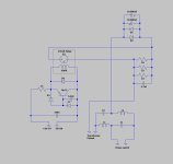
With the info on the PCB pictures I could complete the schematic.
The two 10.000uF are not in series but parallel, so positioning is correct in the picture.
I have re-arranged D3 and D4, to make it more obvious that D4 is to catch the flyback pulse from the relay when switched off and that D3 is to discharge the 6.8uF cap through the relay resistance at switch off.
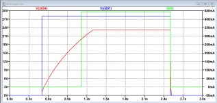
With the given component values and knowing that the 24V Relay has 600R DC resistance, I could simulate the on/off time, see second attachment.
Blue is the rectified voltage from TR1 at switch on and switch off, I assumed it to be 28V.
Red is the voltage on the Relay, limited at 24V by Z1.
Green is the current through the relay while switching on and off.
Switch-on time is ca 0.8sec and switch-off is almost immediate.
Hans
The two 10.000uF are not in series but parallel, so positioning is correct in the picture.
I have re-arranged D3 and D4, to make it more obvious that D4 is to catch the flyback pulse from the relay when switched off and that D3 is to discharge the 6.8uF cap through the relay resistance at switch off.
With the given component values and knowing that the 24V Relay has 600R DC resistance, I could simulate the on/off time, see second attachment.
Blue is the rectified voltage from TR1 at switch on and switch off, I assumed it to be 28V.
Red is the voltage on the Relay, limited at 24V by Z1.
Green is the current through the relay while switching on and off.
Switch-on time is ca 0.8sec and switch-off is almost immediate.
Hans
Attachments
You're incredible Hans!
Your schematic is absolutely right, and its presentation is much more "didactic" than mine. And much easier to understand. And your calculation of the off/on time is probably exact too. I'll try to check with a chronometer if I can 😉
And it's also exact that switch-off is nearly immediate, as far as I can hear.
I don't know where you found the coil resistance value (data sheet?), but it is correct since I measured it at nearly that (597ohm if I remember). I should have this figured on the schema.
Please allow me a newbie question? what's the use of those 2 x 10000µF capacitors? Since it appears that they are not present in all ML-9 (cf Gaetano's own amp), but we can see them in the 23 and the 27...
Thanks once again, I'll redraw the schema I've got with consideration to your (more than) valuable contribution.
Last edited:
First question should be: what are those diodes doing ?what's the use of those 2 x 10000µF capacitors? Since it appears that they are not present in all ML-9 (cf Gaetano's own amp), but we can see them in the 23 and the 27...
They are to block a possible DC voltage offset on the mains supply, thereby preventing the transformer going into saturation.
But since the on-off switching of these diodes may produce HF spikes, the two 10mF caps are there to suppress these spikes.
When using soft recovery diodes, this effect may be diminished but it will not completely remove the spikes.
So maybe ML has been experimenting with different diodes.
Hans
I expect from such expensive Hifi gear that they use first class high grade quality which "never" wears out!
Like the electrolytics in the Viking satellites ;-)
Like the electrolytics in the Viking satellites ;-)
It's very clear Hans. I'm therefore surprised as such a value just to suppress some HF spikes. Would it be that such a capacitor's role is to prevent short-term variations in the load current from becoming voltage spikes? Is its function analog to a capacitor/diode snubber circuit? Would it be interesting then to bypass them with smaller (like film-type) capacitors to improve their HF filtering capacities, or am I completely out of the question? Or even design a RLC filter?
I'm not specialist at all, so pardon my (probably stupid) questions, it's just curiosity. I guess that ML engineers knew what they did when designing such circuits. Have a nice weekend.
I'm not specialist at all, so pardon my (probably stupid) questions, it's just curiosity. I guess that ML engineers knew what they did when designing such circuits. Have a nice weekend.
Probably from a given time on they decided to suppress the little network at all. In the case of my amp the Frako caps as well as the two diodes are just and simply missing, they have never been soldered. I also saw another board from a ML9 in which the area of the caps and the diodes D1 and D2 was occupied by the 33Ohm resistor which is normally right below the relay.First question should be: what are those diodes doing ?
They are to block a possible DC voltage offset on the mains supply, thereby preventing the transformer going into saturation.
But since the on-off switching of these diodes may produce HF spikes, the two 10mF caps are there to suppress these spikes.
When using soft recovery diodes, this effect may be diminished but it will not completely remove the spikes.
So maybe ML has been experimenting with different diodes.
Hans
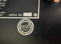
Jerome, given that your amp dates back to 1985, mine probably is from the same year or from 1986, which is already in the Madrigal era. One more little confirmation is coming from a little sticker on the back cover of my amp saying "Mark Levinson" and "Madrigal" right below
Yes Gaetano. Mine has no sign at all of any Madrigal signature. The faceplate is purely Levinson, old address. Madrigal took control of MLAS end of 1984 or at the very beginning of 1985, so I guess it's a madrinson. But I suppose they had numbers of faceplates already made in the factory.
As Hans says, "maybe ML has been experimenting with different diodes"... and different circuits.
As Hans says, "maybe ML has been experimenting with different diodes"... and different circuits.
In my case, trying to estimate relay activation time by a chronometer, I obtain about 1.8 s to switch-on and 0.5s to switch-off.With the info on the PCB pictures I could complete the schematic.
The two 10.000uF are not in series but parallel, so positioning is correct in the picture.
I have re-arranged D3 and D4, to make it more obvious that D4 is to catch the flyback pulse from the relay when switched off and that D3 is to discharge the 6.8uF cap through the relay resistance at switch off.
With the given component values and knowing that the 24V Relay has 600R DC resistance, I could simulate the on/off time, see second attachment.
Blue is the rectified voltage from TR1 at switch on and switch off, I assumed it to be 28V.
Red is the voltage on the Relay, limited at 24V by Z1.
Green is the current through the relay while switching on and off.
Switch-on time is ca 0.8sec and switch-off is almost immediate.
Hans
Gaetano
And I tried yesterday, 1.2s switch on, less than 0.3 switch off… as far as I can switch and count in the same time…
German importer SUN AudioHere is a picture of the sticker which was attached by the importer, most probably.
I like the word madrinson 😀
I've read this thread with much interest and little knowledge/insight on my part that is. 😉
I will get its bigger brother the Levinson ML-3 next Friday and will replace all 40 years old lytics also the big blue Spragues.
So far as I know I do not have those yellow/brown plastic RIFA 4700 pF caps inside:


Madrigal kept on using these caps in their No. XX successors and allegedly they could destroy an amp like the No 23.5.
I will get its bigger brother the Levinson ML-3 next Friday and will replace all 40 years old lytics also the big blue Spragues.
So far as I know I do not have those yellow/brown plastic RIFA 4700 pF caps inside:
Madrigal kept on using these caps in their No. XX successors and allegedly they could destroy an amp like the No 23.5.

Great acquisition, @RobertS61 ! A ML-3 is probably a fantastic amp. All EL caps do not necessarily need a replacement, I'd say. Those which are on the amp PCBs were all fine on my own ML-9. The 672 Sprague probably need a replacement, they don't hold much in time, and the inside temp is high. One of the big cans wasn't too much within specs, but after reforming it is perfect. But I had decided to replace them anyway and as I had ordered Nippon Chemical identical caps, I went on replacing them, as the amp was on the bench.
For your information, the ML-9 are now driving a pair of Apogee Duettas, rather well I'd say. They 'heat' quite much, around 55°C on the heatsinks, which is the maximum I allow them...
Fell free to give us your impressions, advice or questions!
Enjoy!
For your information, the ML-9 are now driving a pair of Apogee Duettas, rather well I'd say. They 'heat' quite much, around 55°C on the heatsinks, which is the maximum I allow them...
Fell free to give us your impressions, advice or questions!
Enjoy!
Thanks. I just finished the revision of the blue Sprague filtercaps.
It's a complete mechanical job of course but it took me 4 hours with this big amp.
The unit was complete original only very dusty so I could clean the inside and the faceplate and handles.
I find this amp very intimidating to work on because everything is so big.
Starting meant a household circuit breaker went out. Had to use a variac...
Impressive, yes!
I remember for the much smaller ML-9, and it was the first "big" amp I was touching.
I would recommend to check the two 672 Sprague on the DCO board. 680µF/6.3V on the ML-9, I guess not much different on the ML-3. If they're old, they are possibly crunched.
I remember for the much smaller ML-9, and it was the first "big" amp I was touching.
I would recommend to check the two 672 Sprague on the DCO board. 680µF/6.3V on the ML-9, I guess not much different on the ML-3. If they're old, they are possibly crunched.
Yes I bought those new but did not have enough energy to solder them out. I will do that of course and thank you for the tip.I would recommend to check the two 672 Sprague on the DCO board. 680µF/6.3V on the ML-9, I guess not much different on the ML-3. If they're old, they are possibly crunched
Your Rifa caps are all okay?
i think this functional description is a bit off.First question should be: what are those diodes doing ?
They are to block a possible DC voltage offset on the mains supply, thereby preventing the transformer going into saturation.
But since the on-off switching of these diodes may produce HF spikes, the two 10mF caps are there to suppress these spikes.
When using soft recovery diodes, this effect may be diminished but it will not completely remove the spikes.
So maybe ML has been experimenting with different diodes.
Hans
it's more that the caps are doing the blocking of DC to the transformer. the rectifiers are there to protect the caps from excessive reverse voltage. we've had long discussions on these circuits in the past on the site. Rob Elliot has a pretty good description of the circuit function with comments about parameters to be careful about here: https://sound-au.com/articles/xfmr-dc.htm. To lend some confidence to the concept, Bryston uses this approach in their amplifiers. Yes, those same amps with the 20 year warranty!
Sorry, I don’t agree.
These caps can never conduct enough current to feed the amp, they are there to make the switch on of the diodes less abrupt.
Hans
These caps can never conduct enough current to feed the amp, they are there to make the switch on of the diodes less abrupt.
Hans
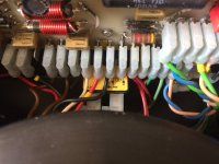
I replaced all Rifa caps. The 5 caps were like they could fail at any moment (see photo attached, it's clear that they are not new!) and while I was there, I replaced them all on the power management board. I put Kemet instead (47n/Y2).Your Rifa caps are all okay?
Attachments
Last edited:
- Home
- Amplifiers
- Solid State
- Mark Levinson ML-9 recapping (1985)