Thank you for your input, analog_sa.
I understand what you mean with the thermal paste. I could add pictures to show that it is maybe a good idea to renew it. And of course if I'd took them out I would do it. Unsure yet if I'm in for that...
The Frako are not on the signal path as far as I understand. But they'll probably need a replacement. I'm still waiting for the NOS I ordered to measure them and make a decision about reforming them or go for another solution.
There is one relay (only one AFAIK, except the ML switch) a Guardian Electric 1365 series which won't be easy to source if necessary. I'm not qualified enough to know if it needs a replacement and even less to figure out how this would better the sound if I'd change it.
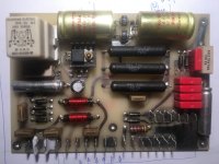
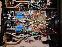
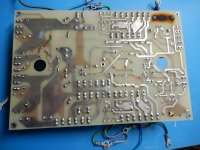
By the way, I just took the transformer out (with the proper adhesive tapes to locate the 20+ contacts when I'll set up all things together later). I could take the regulation board out (the one with the Frako caps) and I add a picture of it.
I understand what you mean with the thermal paste. I could add pictures to show that it is maybe a good idea to renew it. And of course if I'd took them out I would do it. Unsure yet if I'm in for that...
The Frako are not on the signal path as far as I understand. But they'll probably need a replacement. I'm still waiting for the NOS I ordered to measure them and make a decision about reforming them or go for another solution.
There is one relay (only one AFAIK, except the ML switch) a Guardian Electric 1365 series which won't be easy to source if necessary. I'm not qualified enough to know if it needs a replacement and even less to figure out how this would better the sound if I'd change it.
By the way, I just took the transformer out (with the proper adhesive tapes to locate the 20+ contacts when I'll set up all things together later). I could take the regulation board out (the one with the Frako caps) and I add a picture of it.
Attachments
Although my Levinson No. 27 is a bit different from your ML-9, there are many similarities as I'm sure you know. I recently completely replaced all electrolytic caps, even though some still tested fairly well. I did remove the modules from the chassis, and desoldered all of the transistors to allow access to both sides of the boards, because trying to desolder caps from the top would not have been possible.
It was a lot of effort, but paid off because I was able to test each of the output transistors and drivers out of circuit, and found that there were many output transistors that were way out of range, substantially below and mismatched compared to the others. I had only one through-plate for a cap let go on me, but I was able to ensure proper solder connection with the new capacitor.
The main filter caps had to be manufactured, and that took about 3 or 4 months. They are the same used by ML service facilities, but with larger lugs, so I had to enlarge some holes in the ground bars connecting the caps, which was no big deal.
It was a LOT of work, and ML service shops charge a lot for the parts and the work (I was quoted $2,500 - more than the amp cost me), but they also do some updates to the boards which I did not do, and they would not describe.
End result is that the replacement of the bad output transistors probably had a greater positive effect than replacing the caps, only 4 of which were way out of spec., and the amp sounds truly wonderful now. It was a great disappointment to me before this work.
I won't clutter your thread with photos unless you'd like some.
Good luck!
there were many output transistors that were way out of range, substantially below and mismatched compared to the others.
Do you have an explanation for this weirdness? I would think they were never properly matched. Btw the transistors in my Krell also tested all over the place.
Other than age and use, not really. I have to imagine that Levinson was careful about matching, but I've seen first hand that both small-signal and power transistors can drift from performance when they were new.
Be careful not to confuse "power" and "gain" (amplification). Having to turn the volume control up means it has reduced gain (not reduced power capability), and that shouldn't happen without other series symptoms since the amp is a feedback amp. If it does, it could maybe be a connection problem or perhaps a relay contact problem.
Losing power capability wouldn't change how much you have to turn up the knob, it would just make the sound distort when you turned it up higher than the amp can handle. Losing power can happen (and often does), typically because of power supply capacitors. But don't expect the volume setting needed to get it to play to change just from changing the power supply capacitors.
I don't know the details of that amp, but could it be that the amp can be set for "balanced" or "unbalanced" operation? If so and if it is set for balanced but you're feeding it via unbalanced, then the gain would be 6dB low (your volume knob would have to be turned more clockwise to get as much sound as you might expect).
Be careful not to confuse "power" and "gain" (amplification).
I would think he meant "power" in an entirely subjective sense. Clearly the gain cannot change and neither can the power unless the main filter caps were reduced to nothing.
Thks GKTAUDIO for sharing your experience. Even if a n°27 resembles to a ML-9, it seems to be a completely different physical organization inside (and complication is double). But the similarities are interesting to understand, and that you succeeded in rehab your amp? I can understand how you can be happy now and proud of your patience and work.
I think that it would be interesting to add some pictures of your experience in this thread, if you have some. After all, it's about recapping an old ML amp?
Question: how and where could you find the right transistors to match the good ones on the amp?
I think that it would be interesting to add some pictures of your experience in this thread, if you have some. After all, it's about recapping an old ML amp?
Question: how and where could you find the right transistors to match the good ones on the amp?
I also have an early Krell KSA 100 with Frakos. They all had to be chagned a few years sgo. They were almost 40 years old. Also replaced the big can electrolytics with parralled 105C Japaneses caps, chokes, and 90,000 uf of Blackgates.
bwaslo, thank you for your interesting comment. It's like the gain and volume potentiometers on my guitar amps if I read you well.
As analog-sa writes, my feeling is purely and totally subjective and doesn't rely on any measures, which I'm quite unable to do.
What I can say is that it occurred by two times that an amp, an old Mission Cyrus 2, would have a weak output before I replace the two 10000uF power supply capacitors (and others as well). With new caps, such an amp could drive my Apogee Stage not being ridiculous, that it couldn't do (at all) with the old caps.
I didn't measure the cans "alone" yet, I still have to disassemble a few parts to do that, but a quick measure which wires disconnected (except the common bar) show only a few nF on my meter. It doesn't seem much, but I might be wrong in testing. I'll do it seriously asap.
Other subject: diodes on the power regulation board (30S6 rectifiers) . One is dead (at least one). Next message with picture.
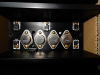
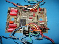
The out of order diodes on the "power regulation" board (dunno of it's a correct designation?)
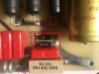
the two 30S6 marked rectifier diodes are out of use. more generally, some of the leads of the diodes on this board are "blackened" like they would have been heating too much. But except tase two, the others seem OK. But I could change them all.
What references would I go for? (datasheet here)
This one could be ok?
Attachments
You showed a circuit diagram for the Amp, do you also have one for the power supply ?
Two anti parallel diodes in a power supply are mostly used in parallel to a resistor that's in series with the mains supply to suppress DC.
If that's the case, it could mean that your supply is only working on half of the 230V/50Hz sine wave !!
Apart from that, there's nothing special to these diodes so easy replaceable.
Hans
Unfortunately no, Hans. What I can do is take a good picture of both sides of the board. I could even - if I take some time to do it - draw the schema. It could help beyond my own problem 😉
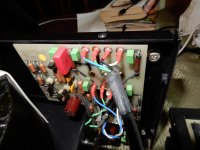
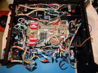
Here is a photo of the 2 diodes with their immediate connexions.
Beside, if my supply has been working on "half" of the sine wave, does it mean that half of the power is delivered? and/or that it could create some "tensions" on other components?
I'm curious to know more about this. As I was surprised to discover these faulty diodes...
Attachments
Hi Perelman,Thks GKTAUDIO for sharing your experience. Even if a n°27 resembles to a ML-9, it seems to be a completely different physical organization inside (and complication is double)...
Question: how and where could you find the right transistors to match the good ones on the amp?
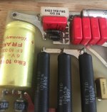
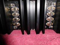
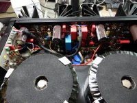
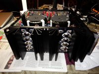
Though the layout differs somewhat, particularly the main filter cap arrangement, the mainboards appear to be very similar in the way they are mated to the heat sinks, and in the mounting of the output transistors through the exterior of the heat sinks. There are other similarities as well. Photos might help. these are just before and during disassembly, showing original caps and transistors.
Fortunately, the output transistors are still in production - MJ15024 and MJ15025. I figured my repair costs were so low compared to what I was quoted for re-capping and updating the input boards but no other parts replacements, that I bought enough replacements to put together matched sets. At first I just replaced the weak/out of spec parts after selecting ones that matched the remaining originals, but then I decided I still had enough money to just replace them all.
Attachments
Last edited:
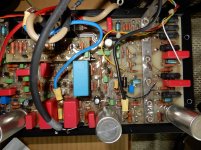
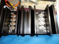
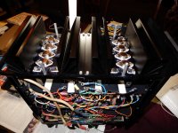
More photos. further disassembly. Burned mark on power board is from LED resistor, which I changed for a higher current one, slightly higher resistance, and elevated off the board, which I sealed with conformal coating.
Attachments
Last edited:
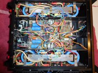
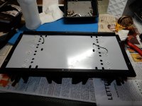
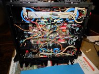
More No. 27 photos. I removed the transformer covers before starting work - they are too pretty to damage. After removing main boards from heat sinks, I completely cleaned the insulating sheet and heat sinks.
Attachments
Last edited:
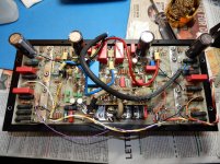
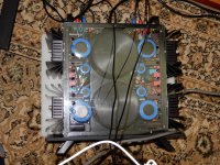
More No. 27 photos. Last two are of the finished amp after initial testing on the bench. The amp is so heavy and large for a 100 wpc amp that it was funny to see it dwarfed by my Conrad-Johnson Evolution 2000, just visible to the right of the amp while I was conducting tests of different preamps with the newly repaired and recapped No. 27.
Attachments

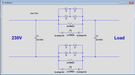
In my amp it's configured like in the image below.
This of course also works with 2 instead of 4 anti par. diodes.
So If one of your 2 diodes is gone, chance is that more components around these diodes are gone, since voltage on these components is no longer restricted to +/- 0.6Volt.
So first try to find the similarity with this circuit.
Hans
This of course also works with 2 instead of 4 anti par. diodes.
So If one of your 2 diodes is gone, chance is that more components around these diodes are gone, since voltage on these components is no longer restricted to +/- 0.6Volt.
So first try to find the similarity with this circuit.
Hans
Attachments
Hi Perelman,
Photos might help. these are just before and during disassembly, showing original caps and transistors.
What a huge amount of wires did you have to move around, my full respect for this complex job.
Hans
Thank you, Hans. It was entirely no fun doing the work. I'm not a fan of the physical design of these amps compared to most others I've worked on. Just too complex and time consuming. However, it was very satisfying when completed, and it's our daily driver. We have 4 systems in rotation just for variety, and this is the lowest power amp we have, but it does a great job with our only moderately efficient speakers and consumes less power.
Perelman, I have a layout drawing for the No. 27 power board which may be somewhat similar to yours, and I think a schematic of that board as well. It might be best if you removed the board so you could trace the diode connections, and you might even want to desolder the diodes to check out of circuit. My main board had 2 diodes that checked as shorted when in circuit but fine out of circuit, due to the parallel connections.
One helpful thing is if you have another amp to use for enjoyment, so you don't rush the repairs. I waited 4 months for caps, then 2 months to finish other projects, then really took my time to work on the ML. The only time I got anxious and rushed was when reassembling and testing, and let a probe slip, which blew out a trace, a diode, and a current source transistor on the main board. That's when I decided to completely disassemble both modules again and replace all of the output transistors, then quadruple-check my work.
Last edited:
- Home
- Amplifiers
- Solid State
- Mark Levinson ML-9 recapping (1985)