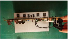
I have found a top view photo of the internals of a PM80 MKII but it is not obvious to me how the transistors fix to the heatsink and what insulation is used , do the heatsinks bend under at the bottom and give a flat surface for mounting to .
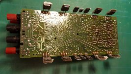
This is a photo of P701 underside. The two heat sinks are straight (walls) on either side, transistor legs bent 90 deg to sit flat against sinks. The three small trans' in the middle use thermal grease, while the power trans' use thermal pads
Attachments
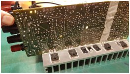
Thanks.... I can see now the PCB sits above the bottom of the heatsinks . Are the transistors then bolted to the heatsinks ?
Suggest put RN05 and 6 back in as the amp needs all the protection back in for a restart .
Suggest put RN05 and 6 back in as the amp needs all the protection back in for a restart .
Found some more substitutes …. 2SC3519 2SA1386 and 2SC3263 2SA1294 . Maybe some of these pairs are easier for you to get hold of .
Thanks.... I can see now the PCB sits above the bottom of the heatsinks . Are the transistors then bolted to the heatsinks ?
Suggest put RN05 and 6 back in as the amp needs all the protection back in for a restart .
Pcb sits about in the middle of heat sinks. Transistors bolted directly to heat sinks.
I want to finish up re soldering but it will take a few days
Found some more substitutes …. 2SC3519 2SA1386 and 2SC3263 2SA1294 . Maybe some of these pairs are easier for you to get hold of .
Thanks. I tried the Canadian place I linked. Fingers crossed. Ordered new ceramic emitter resistors as well
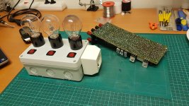
A small update; Finished soldering board P701. Got new power transistors in the mail, still waiting for emitter resistors. Built and tested bulb limiter.
I was wondering about the test mentioned with only one pair of power transistors, any other measurements I should do before and during?
I was wondering about the test mentioned with only one pair of power transistors, any other measurements I should do before and during?
Attachments
ADDENDUM: The YELLOW link will reduce the potential for unplanned output stage destruction (but you're not there yet).
Also I would very much appreciate a elaboration about this trick, what to measure and how to conclude when to remove it
Thanks in advance!
Before this though ( if it is not hard to do ) i would initially repower the amp up ( using the bulb limiter ) with just one pair of output transistors in each channel Q735 , 737 , 736 , 738 ( these have the output current sensing ) just in case there are still problems .
The amp has a double pair of output transistors in each channel which are in parallel so you only need one pair in each channel for power up testing without speakers .
Before power up turn the bias setting pots back to minimum then If you have reinstalled RN05 and 06 and the amp comes out of protection on power up that would be a good indication that it is mostly ok . I would then check the DC output offset voltage and various voltages over the amp just for reassurance . Then tap over the various boards with an old plastic tooth brush handle to check for any further bad joints ( vibration testing ) . All of this with the bulb limiter in use . You could then install all the output transistors and try again . The choice is obviously yours .
I personally would not use the "yellow" straps as they collapse the biasing of all the output devices and this is the area you are trying to prove is now ok . I think the bulb limiting should be sufficient .
PS you have done a neat job on the bulb limiter , I like it .
Last edited:
PS you have done a neat job on the bulb limiter , I like it .
Thanks! Fun little project, witch I should have done earlier.... Oh well, live and learn.
Ok, I will desolder the power transistor pairs that is now sitting on P701 and do as you suggest. RN05 and 06 is back on. While waiting for emitter resistors I guess I can have a closer look at solder joints on all the other boards properly
Thanks for taking your time explaining, I really want to learn in the process and not just make haste to get the amp done. Was wondering if my understanding of Output DC Voltage is correct, as marked in red in picture
Attachments
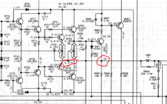
Yes that is what I am referring to . The voltage there should be in the mV region .
Last edited:
Yes that is what I am referring to . The voltage there should be in the mV region .
Update; The DC offset is off the charts - in the twenty volt region. I've measured as far back as R755 and get around 18V. Same value both channnels both +VE and -VE
So obviously the amp does not come out of protection. 60W bulb starts bright but dims to a quite faint glow
Last edited:
Some more observations:
- Rail voltages are low (33V + and -)
- DC offset on outputs are negative, same on both ch
- When using voltmeter between 0V and C701 or C702, voltages drop suddenly - bulb glows bright
Was this not mentioned early in the thread from someone, about some of those caps might leak DC? Edit; John Snell mentioned C711 and C712
Last edited:
What voltages do you get at R755 756 757 and 758 .
R755: -17,5V
R757: -21V
R756: -17,2V
R758: -20V
With no power on check you have a earth/ground on the junction of R706 and R705 where they meet J706 ( main amp board furthest left ) and an earth/ground at J704 ( pin 2 or any component connected to pin 2 ) .
With no power on check you have a earth/ground on the junction of R706 and R705 where they meet J706 ( main amp board furthest left ) and an earth/ground at J704 ( pin 2 or any component connected to pin 2 ) .
R706 and R705 has stable and good ground connection, both resistors have correct value as well.
J704 though, has no ground connection. Or it had some intermittent around 60kohm and slowly rising, like a charging cap
Correct me if I'm wrong, but is there supposed to be a ground connection on pin 2 J704? This comes from main transformer CT (Center Tap I presume). Connection is there to J705 pin 2, witch is called GND, and comes also from CT
BTW; I see there is differences in schematic for PM80 MKII and MKII SE in where GND and CT are on board P851
Last edited:
Both schematics I have both have an earth ground coming in from the right hand side of the board . Does your board have 3 protection relays on the output/speaker side as my other schematic only has 2 .
I don't see a direct connection of ground to centre tap on either 851 board schematics .
I might be wrong, but seems to me there is some anomalies in my SE schematict - some mixups between J802 and J851, witch leads CT to ground on J853
Maybe I could send you my schematic on email or something?
- Home
- Amplifiers
- Solid State
- Marantz PM-80mkII issues (I'm sorta stuck)