Small update. Broke out board P701 to better access transistors and inspect solder joints. Lots and lots of very loose and poor joints. For instance all the transistors in the area around bias pots, like Q711, 713, 717 etc where all so loose that I could with very little effort move them up and down in the PCB-holes.....yikes!
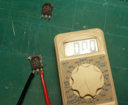
Did the diode-testing as you recommended and there is definitely some different results left and right channel. Did all BC, BE etc. after I had a look at datasheets on the transistors. Many checks out like you said, but looks to me like there is several on L-ch. that is shorted
Should I de-solder them and do a proper test?
Amazing …. so many bad joints it was a accident waiting to happen . Yes remove the suspect transistors and check them out of circuit. Do the right channel transistors check out ok as the comparison is suggesting good verses bad and we are not sure if the right channel is good . I cant believe your bad luck with this amp , like jumping in at the deep end.
PS in diode test mode shorts will read a much lesser voltage than approx. 0.65V even giving 0.0V .
PS in diode test mode shorts will read a much lesser voltage than approx. 0.65V even giving 0.0V .
Last edited:
Do the right channel transistors check out ok as the comparison is suggesting good verses bad and we are not sure if the right channel is good .
I'm not exactly sure if I understood this. Sorry! Language barrier probably 😉
PS in diode test mode shorts will read a much lesser voltage than approx. 0.65V even giving 0.0V .
I got both these readings, but offcourse in circuit. I was a bit uncertain because there was so many anomalies with readings vs. polarity on test leads that I got confused. Ended up doing all combinations one at the time, comparing to other channel, then next transistor. Several on left ch got 0.0V reading both polarities. Guaranteed there is some transistors that are shorted, but off circuit measuring will probably reveal witch...
I cant believe your bad luck with this amp , like jumping in at the deep end.
Hehe, yes I agree! Felt like every step forward forced me two steps backwards.
Last edited:
I'm not exactly sure if I understood this. Sorry! Language barrier probably 😉
We cant be sure the right channel is ok so with some transistors you could be comparing bad with bad but if you can read approx. 0.65V across the BC and BE junctions of all the right channel transistors then it might be fair to assume that as a starting point those transistors are ok .
Also check the protection driver transistors QN01,2 and 3 . Good hunting .
Last edited:
That suggests bad solder joints (a common problem) and/or lifted tracks.Small update. .were all so loose that I could with very little effort move them up and down in the PCB-holes.....yikes!
Should I de-solder them and do a proper test?
As you're going to re-solder multiple joints (you have no choice), you can remove the transistors and test them out of circuit (although a short is a short and is usually obvious when in circuit).
If you understand the Polish language, here are some examples of common issues with Marantz (and other) amplifiers;
Example 1 - watch the LEDs when the resistor is moved.
Example 2 - destruction caused by a loose transistor/bad solder joints (Q719/Q720 in your amp).
Example 3 - clues on how to build and connect your bulb limiter - if you don't have crocodile clips, you can solder the bulb limiter to the fuse terminals (F901 in your amplifier). Don't forget to disconnect mains power and remove F901...).
Before applying mains power, connect your newly constructed bulb limiter between the mains supply and the internal transformer.
Here's an example of what I used in an emergency situation (I'm a cheapskate);
Portable RCD
Bulb holder
I already had 60W incandescent bulbs availale.
I'm sure you'll find equivalent parts in Norway!
Good Luck!(lykke til)
ADDENDUM:
1. No DC on speaker terminals, witch is a good thing I presume
Always measure DC offset between the middle pin of the emitter resistors (4x large white resistors) and 0V.
Last edited:
That suggests bad solder joints (a common problem) and/or lifted tracks.
As you're going to re-solder multiple joints (you have no choice), you can remove the transistors and test them out of circuit (although a short is a short and is usually obvious when in circuit).
If you understand the Polish language, here are some examples of common issues with Marantz (and other) amplifiers;
Example 1 - watch the LEDs when the resistor is moved.
Example 2 - destruction caused by a loose transistor/bad solder joints (Q719/Q720 in your amp).
Example 3 - clues on how to build and connect your bulb limiter - if you don't have crocodile clips, you can solder the bulb limiter to the fuse terminals (F901 in your amplifier). Don't forget to disconnect mains power and remove F901...).
Before applying mains power, connect your newly constructed bulb limiter between the mains supply and the internal transformer.
Here's an example of what I used in an emergency situation (I'm a cheapskate);
Portable RCD
Bulb holder
I already had 60W incandescent bulbs availale.
I'm sure you'll find equivalent parts in Norway!
Good Luck!(lykke til)
Thank you for further tips. I am in the process of gathering parts to make a bulb limiter, although I need to go hunting for bulbs as they are no longer available in the stores. Thinking of building something like in the first video you shared, assuming i can source some bulbs both 40w and 60w
One question regaring the portable RCD. We have those in stores, so no issues there. But am I wrong in assuming this device will not do anything when working on double insulated gear? My amp is double insulated and thus no connection to ground. My understanding is that these devices work the same way the RCD in my mains fuse box, by tripping if a small current is detected between ground/earth and one phase, no?
I do not know polish but only the visuals in the links show exactly the same issues that I'm having. Doing a google session on these amps clearly tells me this is a common issue
BTW; I think your link in "Example 3" is the same as #2
Thanks again for providing great info. Much appreciated!
The bulbs are difficult to source. I had access to 60W &100W bulbs in my workplace - they've long gone!...I am in the process of gathering parts to make a bulb limiter, although I need to go hunting for bulbs as they are no longer available in the stores.
I had to purchase replacement bulbs from an online source. Example
You're correct - the RCD cannot protect you from transformer secondary voltages, but as you've been replacing F901, use a RCD.One question regaring the portable RCD. We have those in stores, so no issues there. But am I wrong in assuming this device will not do anything when working on double insulated gear? My amp is double insulated and thus no connection to ground. My understanding is that these devices work the same way the RCD in my mains fuse box, by tripping if a small current is detected between ground/earth and one phase, no?
Good Luck!
ADDENDUM: Here's my 'emergency' bulb limiter - I haven't even removed the ceiling rose;

If you are already protected by a RCD, you can skip purchasing the portable RCD.
And examples 2 & 3 are from the same video.
Last edited:
And examples 2 & 3 are from the same video.
Got it! I was a bit to quick there
Had a hunt for light bulbs in my house. Found one 60W, one 40W halogen and one 30W halogen - all E27
Bought some switches and some bits. Just need to get a box and some E27 sockets. I guess this device could be useful later if I should decide to build some tube amp stuff
A quick update: De-soldered all power transistors and Q719, 720, 727, 728, 730 (witch I'm not sure what to call)
Q737 and 736 is shorted in all junctions.
Did all the diodes - OK
All the rest of transistors - OK
I also checked the electrolyte caps like we used to do back in school days eons ago, in and out of circuit. We only did this with small ones. Short the pins, measure with multimeter in ohm, watch resistance gradually increase to big numbers. Small caps faster than larger ones. Is this a valid test method, or where we just young and dumb back then?
All caps on P701 reacted so I would deem them OK
Attachments
Just to clarify are the faulty power transistors from different channels .
Yes, that is correct. PNP from one, and NPN from the other.
I see you removed Q719 and Q720 , those will test differently as they are darlington transistors BC junction approx. 0.65V... BE approx. 1.3V... EC open circuit.... all open circuit in reverse polarity .
PS check the resistance of all the low ohm resistors around the power transistors 10 ohm , 150 , 1000 and particularly the 0.18 ohm cement resistors ( check they are all 0.18 ohm to there relevant output rails ) .
PS check the resistance of all the low ohm resistors around the power transistors 10 ohm , 150 , 1000 and particularly the 0.18 ohm cement resistors ( check they are all 0.18 ohm to there relevant output rails ) .
Last edited:
Will do! do I need to de-solder resistors? Usually they measure slightly below they're value in circuit if I'm correct
As suggested, ALL resistors within the BLUE areas need to be checked.
As you've found output transistors with Collector-Emitter shorts, the resistors in the RED box have been severely stressed and possibly destroyed. Check each section of R781-R784 (de-solder if necessary).

And you're correct - whilst 'in circuit' a resistor can NEVER measure more than its stated value (plus tolerance).
Good Luck!
ADDENDUM: The YELLOW link will reduce the potential for unplanned output stage destruction (but you're not there yet).
As you've found output transistors with Collector-Emitter shorts, the resistors in the RED box have been severely stressed and possibly destroyed. Check each section of R781-R784 (de-solder if necessary).
And you're correct - whilst 'in circuit' a resistor can NEVER measure more than its stated value (plus tolerance).
Good Luck!
ADDENDUM: The YELLOW link will reduce the potential for unplanned output stage destruction (but you're not there yet).
Thanks!
I have some work ahead of me. Started de-soldering all joints last night with solder wick, brushing and re-solder. Time consuming stuff, but have to be done.
I was wondering if you guys had some tips for where to order power transistors from? ebay has plenty but I don't thrust those cheap ones to be genuine Sanken. Sent a request on digikey but have not heard back. There is a Norwegian iteration of digikey, but they state 5 month delivery time witch seems pointless
Maybe these guys?
2SA1694 2SC4467 Transistors Pair – KP Components Inc.
Last edited:
I have found possible substitutes if the above proves unreliable .
2SA1941 2SC5198 and 2SA1943 2SC5200 the later options come in 2 different packages though one the same as yours and the other a bit larger
2SA1941 2SC5198 and 2SA1943 2SC5200 the later options come in 2 different packages though one the same as yours and the other a bit larger
Last edited:
I have found possible substitutes if the above proves unreliable .
2SA1941 2SC5198 and 2SA1943 2SC5200 the later options come in 2 different packages though one the same as yours and the other a bit larger
Would I need to change out both channels so they are equal, or are equivalents exactly the same?
BTW; one of the ceramic 2x0,18ohm emitter resistors are busted and need replacement. A google session yielded no results, but I could use two of these couldn't I? 0.18 ohm 3W (watt) for 2pcs Ceramic collector–emitter Cement RESISTOR | eBay
Would I need to change out both channels so they are equal, or are equivalents exactly the same?
No ….. suggest you would make up one channel with the originals and just put one new pair ( as a pair ) in the other ( one NPN one PNP ) to replace the faulty ones . Before this though ( if it is not hard to do ) if would initially repower the amp up ( using the bulb limiter ) with just one pair of output transistors in each channel Q735 , 737 , 736 , 738 ( these have the output current sensing ) just in case there are still problems .
I have found a top view photo of the internals of a PM80 MKII but it is not obvious to me how the transistors fix to the heatsink and what insulation is used , do the heatsinks bend under at the bottom and give a flat surface for mounting to .
Yes those resistors would be ok , axial ceramic versions might be easier .
Last edited:
- Home
- Amplifiers
- Solid State
- Marantz PM-80mkII issues (I'm sorta stuck)