Re: Re: RCh problem in cd63ki
Hi Ray,
Thanks a lot for your timely guidence. I checked and found Q606 the culptrit. Yet to source replacment opamps. I did not do any mod but I am very much charged to do, after going through this thread. Sourcing all components required is a big problem in India.
Regards
Yash
6h5c said:
Hi Yash,
That's a printing error in the schematic. Pin 8 of Q105 is tied to pin 1, creating a buffer. This drives the laserdiode. The voltage on these pins is either 0V or 5V, for STOP and PLAY mode. This section has nothing to do with your muffled sound problem. The other components (RD14 and U193) are feeding the clock signal from the DAC to the decoder. If you touch them, you disturb this high frequency signal, and this causes the player to malfuntion. This is normal, just like the different values.
You should take a good look at the components after the DAC outputs, around Q605/606. Did you modify anything in this area? Or is it a blown tweeter of one of your speakers 😀 ?
Regards,
Ray
Hi Ray,
Thanks a lot for your timely guidence. I checked and found Q606 the culptrit. Yet to source replacment opamps. I did not do any mod but I am very much charged to do, after going through this thread. Sourcing all components required is a big problem in India.
Regards
Yash
Re: Re: CD67SE muffled channel output
Hi Pete,
Seems you're having bad luck! The fact that the other laserunit has the same problem indicates that it is on the main PCB. Did you check the flatcables? They can give trouble sometimes. They are not made to be taken in and out so much times. If you installed an external clock, check the connections or the signal is arriving at the DAC and decoder. It seems the servo is "on the loose", it happens also when the clock is not present.
Regards,
Ray.
Chivvyp said:Everytime I take this apart and rebuild it something else goes wrong!
Now I have a problem with the laser, as soon as I switch the player on the small mechanism around the lens starts "hopping" with a loud clicking noise. I don't think it's a problem with the laser as I replaced it with an old one (old one was faulty, generally played ok but wouldn't play some cds/tracks but didn't have this hopping/clicking symptom) and had exactly the same problem.
Anyone have any ideas what could be causing this?
Regards
Pete
Hi Pete,
Seems you're having bad luck! The fact that the other laserunit has the same problem indicates that it is on the main PCB. Did you check the flatcables? They can give trouble sometimes. They are not made to be taken in and out so much times. If you installed an external clock, check the connections or the signal is arriving at the DAC and decoder. It seems the servo is "on the loose", it happens also when the clock is not present.
Regards,
Ray.
Re: Re: Re: CD67SE muffled channel output
Hi Ray,
The ribbon cables are ok, I checked continuity between the two sockets with a DMM. I have installed a seperate clock but I think that's working ok as I was getting (some) sound before this last dismantle. By eyesight it looks to be connected correctly. Is there a simple way to test if the clock signal is getting to the dac and decoder?
Browsing through this thread I think Simon had a similar problem at one time which was (maybe) down to loose/bad connection to the JM01 socket in the board. I plan to examine that at the weekend!
Thanks for the advice.
Pete
6h5c said:
Hi Pete,
Seems you're having bad luck! The fact that the other laserunit has the same problem indicates that it is on the main PCB. Did you check the flatcables? They can give trouble sometimes. They are not made to be taken in and out so much times. If you installed an external clock, check the connections or the signal is arriving at the DAC and decoder. It seems the servo is "on the loose", it happens also when the clock is not present.
Regards,
Ray.
Hi Ray,
The ribbon cables are ok, I checked continuity between the two sockets with a DMM. I have installed a seperate clock but I think that's working ok as I was getting (some) sound before this last dismantle. By eyesight it looks to be connected correctly. Is there a simple way to test if the clock signal is getting to the dac and decoder?
Browsing through this thread I think Simon had a similar problem at one time which was (maybe) down to loose/bad connection to the JM01 socket in the board. I plan to examine that at the weekend!
Thanks for the advice.
Pete
Re: Re: Re: Re: CD67SE muffled channel output
If you have a 'scope it's simple.
Chivvyp said:
Is there a simple way to test if the clock signal is getting to the dac and decoder?
Pete
If you have a 'scope it's simple.
I picked up 3 Black Gate Std 16V 470uF caps to meet a minimum order with an Australian distributor when I bought the Brown Dog adapters.
These I assume are polar caps. Are all the caps on the CD63KI polar, or do I need to be careful which ones to put in?
Also, where would be the best place to put these caps to get the maximum benefit?
When I go to solder the Opa627's to the adapter, is it better to use a hotter iron for a shorter period or less heat for longer?
Thanks,
Simon
Phew!!
I've just finished reading through all the posts in this thread and now I'm up to date. I realise I've asked questions that have already been dealt with. My apologies.
I've saved pages that I think are very useful so I can come back to them, as well as attachments that people have provided.
Thanks very much to the experts who have contributed great knowledge and also to those like me who have very little experience in mods who asked the right questions.
Simon
At the risk of being crucified for mentioning the word Burson, I mentioned earlier I was waiting for a pair of their HDAM and buffers, said I would post what they sounded like. The HDAM's are actually quite nice. Much more midrange character than 2xOPA627 yet preserving nice detailed highs. 627's sound a bit brittle compared to these. Initially there was a bloated low mid thing going on (250-400Hz) but that has since subsided. From what I have been able to decipher from the Audio-gd website you are able to flavor these to taste. Unfortunately one of the buffers was defective and can't comment untill a replacement is sent. I found out about the Burson/audio-gd/Heqinghua relationship shortly after my last order. Some of the items look identical to Burson while others do not. Would be intertested to hear if anyone has actually ordered something from the audio-gd folks, there certainly is a difference in price. All in all the stuff I used from Burson- clock,PS's, regs, HDAM's sound excellent in my 63.
YoungSC said:I picked up 3 Black Gate Std 16V 470uF caps to meet a minimum order with an Australian distributor when I bought the Brown Dog adapters.
These I assume are polar caps. Are all the caps on the CD63KI polar, or do I need to be careful which ones to put in?
Also, where would be the best place to put these caps to get the maximum benefit?
When I go to solder the Opa627's to the adapter, is it better to use a hotter iron for a shorter period or less heat for longer?
Thanks,
Simon
Hi Simon,
I'd say put those BG caps around the DAC. That's a noisy part of the circuit. Or use them around the opamps. But then you need four of them. All caps are polar by the way, so watch the minus!
When soldering SMD's, don't set your iron too hot. Very little heat is needed for the small contacts. A short heat-time is good, but let the solder flow enough to make a good connection.
Regards,
Ray
Re: Re: Re: CD67SE muffled channel output
Hi Ray,
Turns out it was the clock signal as you diagnosed. The solder ring around the pcb hole where it was connected had disappeared (seems to happen fairly easily, it's not the first time I've had problems with them) so I had to connect it directly to the DAC pin.
Now it's all working, just a problem with channel out of balance to try to solve before I put the lid back on.
🙁
Thanks for the advice
Pete
6h5c said:
Hi Pete,
Seems you're having bad luck! The fact that the other laserunit has the same problem indicates that it is on the main PCB. Did you check the flatcables? They can give trouble sometimes. They are not made to be taken in and out so much times. If you installed an external clock, check the connections or the signal is arriving at the DAC and decoder. It seems the servo is "on the loose", it happens also when the clock is not present.
Regards,
Ray.
Hi Ray,
Turns out it was the clock signal as you diagnosed. The solder ring around the pcb hole where it was connected had disappeared (seems to happen fairly easily, it's not the first time I've had problems with them) so I had to connect it directly to the DAC pin.
Now it's all working, just a problem with channel out of balance to try to solve before I put the lid back on.
🙁
Thanks for the advice
Pete
YoungSC said:I picked up 3 Black Gate Std 16V 470uF caps to meet a minimum order with an Australian distributor when I bought the Brown Dog adapters.
These I assume are polar caps. Are all the caps on the CD63KI polar, or do I need to be careful which ones to put in?
Also, where would be the best place to put these caps to get the maximum benefit?
When I go to solder the Opa627's to the adapter, is it better to use a hotter iron for a shorter period or less heat for longer?
Thanks,
Simon
I would drop these in around the DAC CD07 , CD15 and CD16. Also you need to change CD04 with something better.
I find 400 deg c with a fine tip ans quickly run the solder in. You have to find the optimum temp for the solder to run freely without boiling the flux out of the solder. It also depends on the size of your tip. Bigger tips keep their temp better when soldering so require a lower setting.
Brent
Re: Re: Re: Re: CD67SE muffled channel output
Hi Pete,
Good to hear you have it running again. The PCB tracks are damaged very easily indeed. You have to be very careful not to put force on them, and use a moderate soldering temperature. The difference in balance could be caused by one of the filter components that's not properly connected.
Regards,
Ray
Chivvyp said:Hi Ray,
Turns out it was the clock signal as you diagnosed. The solder ring around the pcb hole where it was connected had disappeared (seems to happen fairly easily, it's not the first time I've had problems with them) so I had to connect it directly to the DAC pin.
Now it's all working, just a problem with channel out of balance to try to solve before I put the lid back on.
🙁
Thanks for the advice
Pete
Hi Pete,
Good to hear you have it running again. The PCB tracks are damaged very easily indeed. You have to be very careful not to put force on them, and use a moderate soldering temperature. The difference in balance could be caused by one of the filter components that's not properly connected.
Regards,
Ray
And thankyou Brent 🙂
I'm still waiting for my friend to get back to me to help install the components. He runs his own business and has been working 7 days a week for a while.
In the meantime, I'm building some quadratic diffusers.
Simon
I'm still waiting for my friend to get back to me to help install the components. He runs his own business and has been working 7 days a week for a while.
In the meantime, I'm building some quadratic diffusers.
Simon
6h5c said:Hey, our thread has almost moved to the third page! Time for a new post, allthough it's a bit off-topic: I've got a new toy 😀 !!
Ray
Hi Ray!
How does it sound??
SimontY said:Hi Ray!
How does it sound??
Hi Simon,
I just got it yesterday evening, and I worked all day, just finished my dinner right now, so I don't know yet! What am I doing here sitting and typing this! Of course: informing everybody about this great news, and hoping to create some envy 😀.
Ray
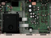
Nice player Ray, lets see it under the hood.
BTW and OT, Simon, are you still using the project88? If so, ever considered going passive? I'm using a passive shunt now, great sound! Wired like this: http://www.world-designs.co.uk/forum/showthread.php?t=198
BTW and OT, Simon, are you still using the project88? If so, ever considered going passive? I'm using a passive shunt now, great sound! Wired like this: http://www.world-designs.co.uk/forum/showthread.php?t=198
avr300 said:Nice player Ray, lets see it under the hood.
Here's a nudie picture 🙂
Lot's of caps, more voltage regs and ferrite shielding around the flatcables. The servo and driver electronics is mounted on a PCB under the transport. So the PCB is mainly PSU, DAC and analog. The digital-out is nicely shielded under a HDAM can. And: no opamps!
This pic is from the Marantz website, there are actually three cans in the player.
Ray
Attachments
Excellent Ray.
It looks a little like the setup of a cd6000 SE/KI with all the HDAM modules.
It should make a good project with excellent gains.
Brent
It looks a little like the setup of a cd6000 SE/KI with all the HDAM modules.
It should make a good project with excellent gains.
Brent
avr300 said:Nice player Ray, lets see it under the hood.
BTW and OT, Simon, are you still using the project88? If so, ever considered going passive? I'm using a passive shunt now, great sound! Wired like this: http://www.world-designs.co.uk/forum/showthread.php?t=198
I used to run passively but I liked the sound of the preamp. It gave it much needed balls. It was gutless without it, albeit with much lower distortion!!
Can you have it both ways?

What I will do is ditch the Project 88 and just use a simpler single op-amp with maybe 6db of gain. I think that would be close to ideal in my system.
Simon
- Home
- Source & Line
- Digital Source
- Marantz CD63 & CD67 mods list