Re: Re: Re: Re: Newbee onboard...
I'll do the test. Have ordered a load of ZL and Pany FC's. Mainly for PSU and analog - but enough so the whole PCB can be done.
disco said:
Hi AVR,
Marantz used 'general purpose' caps everywhere, except for the opamps and HDAM. Right now I am replacing caps with both low ESR (Elna RJH, BG, Panasonic FC) and new general purpose (Nichicon RZm).
Replacing with GP in some places doesn't harm audio as I auditioned both of them.
I don't know what the effects will be of replacing all caps with ultra low impedance like Rubycon ZL/ZLH as the ultra low impedance is a heavier load to the PSU. Has anybody experimented with this setup?
Regards, Jaap
I'll do the test. Have ordered a load of ZL and Pany FC's. Mainly for PSU and analog - but enough so the whole PCB can be done.
Re: Re: Effects of damping the chassis
There is not much (public) background on the effects of vibration in the CD player. What I did found was that optical parts suffer most from vibration. They can be separated into A: vibration originating from the motors and B: vibration passed through via the chassis.
To lower the effects of vibrating motors one could make the transport heavier. To guard against chassis vibration one could isolate the transport from the cassis.
Re: Re: Effects of damping the chassis
By adding weight you lower the selfresonance of the case. The damping effect is measured both in time (how long the lid is ringing) and dB (how loud it is ringing). Undoubtedly there exists an optimum point in applied materials.
Regards, Jaap
Hi Simon,SimontY said:My best guess is it's more relevant to the analogue parts, as damping effects are heard with amplifiers too. Maybe the transport likes it too 😉
This feeling is compounded by me putting way too much bitumen inside (2/3 layers on lid) and the sound becoming dead and dry. Yes, I believe you can overdamp it. Let the flames begin...
By adding weight you lower the selfresonance of the case. The damping effect is measured both in time (how long the lid is ringing) and dB (how loud it is ringing). Undoubtedly there exists an optimum point in applied materials.
Regards, Jaap
Re: Re: Re: Effects of damping the chassis
As far as the Xtal is concerned there might be some forces at work degrading it's good behavior.
First there is movement caused by mechanical disturbance. Permanent frequency offsets due to shock can be caused by changes in the oscillator circuitry (eg, due to movement of a wire or circuit board). Resonances in the mounting structure will amplify the shock-induced stress.*
Furthermore it's possible that the frequency stability of the Xtal is compromised by acoustic noise. For this purpose I build a housing to shield (a little) against airpressure variations.
Although not huge the effect is noticeable in clearity and detail. I'm not shure it's the lesser HF radiation or diminished influence of acoustic noise that plays a role on the reproduction.
Jaap
* http://www.ieee-uffc.org/freqcontrol/quartz/vig/vigaccel.htm
Attachments
6h5c said:
Oh, o.k. I guess I missed that part 🙂.
So Brent, why are you modding the communication lines with coax? 😀
Ray.
Did some more reading around this thread, man it is huge!!! 😀
In the pdf you posted from the bobwire 63 mods, bobwire is also talking about putting coax at the dac at pin 11 and 12 (communication lines). Bobwire is talking about great gains with these.
Bobwire is also suggesting to remove the series resitors for these lines completely.
gy21 said:In the pdf you posted from the bobwire 63 mods, bobwire is also talking about putting coax at the dac at pin 11 and 12 (communication lines). Bobwire is talking about great gains with these.
Bobwire is also suggesting to remove the series resitors for these lines completely.
You're right, it just occurred to me (wake up, dude!). There's data going over them continuesly in play-mode, and not just during power-up and manual/remote control. So my previous statement was wrong
 .
.For the DAC only the volume control and initialisation is done, but the decoder, servo and CPU are constantly talking to each other. These two lines form a I2C-bus between multiple IC's, so the data is going everywhere, also to the DAC, even if it is not adressed. Duh!
Replacing them with coax may well be worth while.
Regards,
Ray.

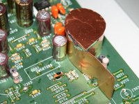
avr300 said:Had a few minutes and a bunch of WIMA films to spare this morning.
It's got the red plague! 😡
The Service Manual mentions 47nF everywhere but instead mine had 22nF all over the board. I guess you take 100nF?
disco said:
It's got the red plague! 😡
The Service Manual mentions 47nF everywhere but instead mine had 22nF all over the board. I guess you take 100nF?
33nF and a couple of 100nF.
Yes it's red and it's
 😡 but 😎
disco said:
It's got the red plague! 😡
The Service Manual mentions 47nF everywhere but instead mine had 22nF all over the board. I guess you take 100nF?
yours was probably made on Monday
they only had 22nf's till the order came in on wednesday

allan
awpagan said:yours was probably made on Monday
they only had 22nf's till the order came in on wednesday
allan
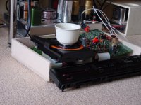
Looking at the chassis mine must be made on a sundaymorning, after a heavy party
Trying something out w.r.t. vibes and it looks like this

Attachments
avr300 said:Fleas on top and red plague under the PCB.
Soon all hope is out.
har har har!
disco said:
Looking at the chassis mine must be made on a sundaymorning, after a heavy party
Trying something out w.r.t. vibes and it looks like this
Now thats a useful way to add mass to the disc clamp
Does it make coffee too?
allan
ps this match between Ned and Aust on now.
Aust is using there swimming team at present, So Much Diving

Step 01
Hello 🙂
Here is the current face of my CD53 (my seller told me then he was selling me a CD53 MkII but Marantz didn't wrote it yet on the CD, so sold me my CD53 indeed a MkII for the price of the CD53, and not the MkII that was sold more expensive in France... and according to your PCB numbers it is a MkII...).
Whatever for you to check I've done no mistake :
Also, does this ferrite (french word ?) or such (I've many) can be used anywhere ?
Hello 🙂
Here is the current face of my CD53 (my seller told me then he was selling me a CD53 MkII but Marantz didn't wrote it yet on the CD, so sold me my CD53 indeed a MkII for the price of the CD53, and not the MkII that was sold more expensive in France... and according to your PCB numbers it is a MkII...).
Whatever for you to check I've done no mistake :
An externally hosted image should be here but it was not working when we last tested it.
Also, does this ferrite (french word ?) or such (I've many) can be used anywhere ?
Re: Step 01
Ah, yet another virgin plane of PCB, waiting to be mounted with a discrete transistor output stage....
Ray.
Malefoda said:
Ah, yet another virgin plane of PCB, waiting to be mounted with a discrete transistor output stage....
Ray.
Re: Step 01
Hi Matthieu,
You can clamp the ferrite on the mains cord, or wind it through two times if that fits. It will suppress some HF noise.
Regards,
Ray.
Malefoda said:Also, does this ferrite (french word ?) or such (I've many) can be used anywhere ?
Hi Matthieu,
You can clamp the ferrite on the mains cord, or wind it through two times if that fits. It will suppress some HF noise.
Regards,
Ray.
Done !
Still have these longing to be used...
About music, it seems the bass guy is coming out of the closet... he's ont the way of the stage, not yet in... tonight'll spent on Farnell's website 🙂
Thank you guys !
An externally hosted image should be here but it was not working when we last tested it.
Still have these longing to be used...
An externally hosted image should be here but it was not working when we last tested it.
About music, it seems the bass guy is coming out of the closet... he's ont the way of the stage, not yet in... tonight'll spent on Farnell's website 🙂
Thank you guys !
6h5c said:
You're right, it just occurred to me (wake up, dude!). There's data going over them continuesly in play-mode, and not just during power-up and manual/remote control. So my previous statement was wrong
For the DAC only the volume control and initialisation is done, but the decoder, servo and CPU are constantly talking to each other. These two lines form a I2C-bus between multiple IC's, so the data is going everywhere, also to the DAC, even if it is not adressed. Duh!
Replacing them with coax may well be worth while.
Regards,
Ray.
Thanks Ray,
Is it the best to connect the coax on one side or on both sides?
gy21 said:
Thanks Ray,
Is it the best to connect the coax on one side or on both sides?
I always gnd the coax at the source end, using the principle of a drain like in interconnects.
Brent
- Home
- Source & Line
- Digital Source
- Marantz CD63 & CD67 mods list