Re: Re: Re: Re: Serious testing...
will do
i need to get the turnable running again, or more precise, make a riaa circuit for the preamp
allan
rowemeister said:
I have some Herbie Hancock, let me know which album and track you recommend 😉
Brent
will do
i need to get the turnable running again, or more precise, make a riaa circuit for the preamp
allan
6h5c said:
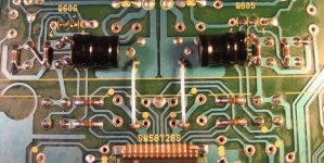
Do you know what power supply this clock needs? If it's 12V, you can tap power in the player from C813, there's about 11VDC there, should work fine. You can connect the clock's + to U268 (the plus of C813), and the GND to U267 (the minus of C813). See picture. But the best solution is to use a separate power supply with a small PCB transformer and a regulator.
You can connect the clock's output signal to the player by removing CD02, CD03, XD01, RD02 and U209. Connect the output of the clock to the hole of U209 that's next to CD05.
If you drop me an e-mail I can send you the CD67 schematics if you like. That might enlighten things a bit.
No problem! Glad to be of help.
Regards,
Ray.
I get why cd02, cd03, xd01 should be removed. But why should rd02 and u209 be removed?
I'm installing a tent xo tonight and the tentlabs instructions do not talk about removing these parts. So therefor my question on this.
gy21 said:
I get why cd02, cd03, xd01 should be removed. But why should rd02 and u209 be removed?
I'm installing a tent xo tonight and the tentlabs instructions do not talk about removing these parts. So therefor my question on this.
HI.
U209 does not really need to be removed but if not, it acts as an antenna !
RD02 is not actually required at all. The internal inverter already has a resistor built-in which performs the same function ie. it biases the inverter into linear mode so it acts as an amplifier. It is more 'belt and braces' than functional !
Andy
FET output stage
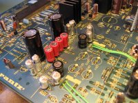
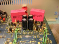
Finally the parts I ordered arrived yesterday, so I could finish the player with the FET-stage i'm working on.
I built a new, serious version of the passive filter part, with 1% PS caps, precision resistors and matched inductors. I've just spent an hour listening to it. Wow. Guys, you really should try this.
The clarity, resolution, it's great. It beats the hell out of my opamp setup.
Attachments
Nice one Ray!
Why don't they make them like that to begin with?
The part count looks low.
Simon
Why don't they make them like that to begin with?
The part count looks low.
Simon
beware
once you go discrete
very hard to go back to opamps
ray
very clean and professional looking work😀
now what to use all those spare holes for
allan
once you go discrete
very hard to go back to opamps
ray
very clean and professional looking work😀
now what to use all those spare holes for
allan
SimontY said:Nice one Ray!
Why don't they make them like that to begin with?
The part count looks low.
Simon
awpagan said:ray
very clean and professional looking work😀
allan
Thanks guys,
The filter part is very easy. Building the FET-stage using the HDAM lay-out is a bit tricky.
But it fits without cutting any traces 😀.
I use some MKC output caps that I had, but I think i'm going to put in some Auricaps, or Reliable.
Maybe i'm even going to put those nice shiny metal cans back....
Ray.
Attachments
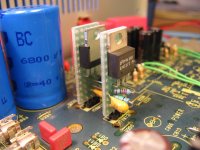
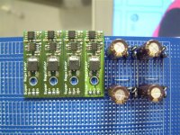
6h5c said:I use these DIY LM317/337 regs for the +/-12V power supply. I guess with better regs the sound will improve even more.
simple plug in replacement
i like them😀
the regs arn't to bad.
try giving the regs a clean earth point.
allan
6h5c said:I use these DIY LM317/337 regs for the +/-12V power supply. I guess with better regs the sound will improve even more.
Looks very nice ray!
Can you post the vero layout or schematic for your diy reg's?
Thanks in advance!
Hi Dave,
What voltage(s) does your clock need? At C803/804 you'll find close to +/-24V depending on their size, after Q801/802 it's +/-12V. I wouldn't recommend tapping it from there, since that is the analog supply, but it will do no harm, it's temporary. If the clock needs only a single supply you can tap it from C813, it's around 12V there.
Regards,
Ray.
Hi Ray it needs both +12v/-12v can be as high as 15vdc
Thanks Dave
6h5c said:
Thanks guys,
The filter part is very easy. Building the FET-stage using the HDAM lay-out is a bit tricky.
But it fits without cutting any traces 😀.
I use some MKC output caps that I had, but I think i'm going to put in some Auricaps, or Reliable.
Maybe i'm even going to put those nice shiny metal cans back....
Ray.
i'm using wima MKC4 4.7uF out.
was thinking of solen.
allan
awpagan said:simple plug in replacement
i like them😀
the regs arn't to bad.
try giving the regs a clean earth point.
allan
Yeah, the are not that bad 😀
But I want to try the Tentlabs shunt regulators in the near future, see if that changes things even more positive.
After my output-stage fever has cooled down i'm going to take a look at the ground plane/star point stuff.
Ray.
6h5c said:After my output-stage fever has cooled down i'm going to take a look at the ground plane/star point stuff.
lol, I'm curious to know your thoughts on better grounding (how it should be done and what gains you hear). Will look forward to that.
Will take a pic of my madness this evening 😎
Si
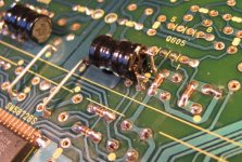
Not quite as exciting as Rays discrete output but I thought I would keep people informed of my latest advantures.
Here is a pic of my Servo , RF and HF reg pcb thats going to replace the existing one.
Ive used Schottky diodes and silmic caps with audiocom super regs.
Here is a pic of my Servo , RF and HF reg pcb thats going to replace the existing one.
Ive used Schottky diodes and silmic caps with audiocom super regs.
Attachments
rowemeister said:Not quite as exciting as Rays discrete output but I thought I would keep people informed of my latest advantures.
Here is a pic of my Servo , RF and HF reg pcb thats going to replace the existing one.
Ive used Schottky diodes and silmic caps with audiocom super regs.
Is that what Warren G meant by Regulate, as in "regulatoooors, mount up.."?
You think Warren G and Nate Dog considered Audiocom regs?


gy21 said:Looks very nice ray!
Can you post the vero layout or schematic for your diy reg's?
Thanks in advance!
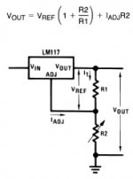
Hi,
I used the standard LM317/337 circuit, with 120R for R1 and a fixed 1k04 for R2. I decoupled the adjust pin with a 10uF tantalum cap to GND.
Attachments
- Home
- Source & Line
- Digital Source
- Marantz CD63 & CD67 mods list