rowemeister said:
Thats how much room I have
Also I meant custom TX as its not the Marantz one!
An externally hosted image should be here but it was not working when we last tested it.
An externally hosted image should be here but it was not working when we last tested it.
"have you run out of room at the back for transformer space?
what ever happen to the custom transformer"
I guess that means no?😀
you have been a busy boy, havn't you
allan
Dr.Gone said:
I'll bid 110, I see some nice components to be salvaged
😉
hehe 😀
I think its worth at least £125 😀
rowemeister said:
hehe 😀
I think its worth at least £125 😀
?????auction????
hehe
allan
awpagan said:
"have you run out of room at the back for transformer space?
what ever happen to the custom transformer"
I guess that means no?😀
you have been a busy boy, havn't you
allan
Yes fairly lol.
The reg pcb on the left is the one being changed for all Audiocom regs soon.
Brent
Gooch said:rowemeister
You have plenty of room to put more stuff in there 😀
Leaving area behind opamp incase I go tube etc
Brent
Gooch said:So can you still put the cover on?
Yes, lol
The caps on the pcb at the front of cdp clear the lid by approx. 1-2mm
The deadening material on strut brace and lid touch nicely helping with the whole resonace control.
You can see why it weighs 7.18Kgs lol
Brent
Mine weighs also 7kg 🙂
Next mod done.
* Disabled the headphone circuit.
Do not directly hear much difference, but it is probably a smaller mod, soundwise.
Next mod done.
* Disabled the headphone circuit.
Do not directly hear much difference, but it is probably a smaller mod, soundwise.
Hey all
I re-soldered the clock on today with new cat5 cable used. Replaced the jumpers u139/140 with some cat5 cable too, and resoldered a large number of joints aroun the transports connection to the main pcb, and around Q105.
When i plugged it back in after all of the re-soldering the mechanism stopped trying to move backwards and forwards. Instead teh disc span up, and kept on spinning faster and faster and faster, until the whole thing nearly shook itself to pieces 😕 😕 😕
What do you suggest i do next, as ive pretty much given up with this one and am tempted to jsut get another 63 and put my mods into that CAREFULLY, as i have too much work in over the coming weeks to bother to fiddle around with this one?
thanks
adam
one more thing. I then took the crazy sppedy transport out and measured the voltages of the pins of Q105. Pretty much all of them had no reading at all. Weird.
adfinni said:Hey all
When i plugged it back in after all of the re-soldering the mechanism stopped trying to move backwards and forwards. Instead teh disc span up, and kept on spinning faster and faster and faster, until the whole thing nearly shook itself to pieces 😕 😕 😕
What do you suggest i do next, as ive pretty much given up with this one and am tempted to jsut get another 63 and put my mods into that CAREFULLY, as i have too much work in over the coming weeks to bother to fiddle around with this one?
thanks
adam
one more thing. I then took the crazy sppedy transport out and measured the voltages of the pins of Q105. Pretty much all of them had no reading at all. Weird.
Hi,
I sent one of my players into warp mode about a month ago.
It was a problem with the clock.
Where did you attach the clock output, and ground?
Clock output goes into the top hole of xd01, and the ground into the right hole of cd03. This will be annoying if my clock is dead ?
ta
ta
adfinni said:Clock output goes into the top hole of xd01, and the ground into the right hole of cd03. This will be annoying if my clock is dead ?
ta
Hi,
Clock needs to feed into pin 28 as per attached notes from Marantz cd63 service manual, and SM5872 datasheet.
http://www.tentlabs.com/Support/Mounting/XO2mounting.pdf
Attachments
Cheers ash
Well i wanted to eliminate the clock from the running of 'cdp killer', so put back in the old one. I put back XD01, CD02/03, and RD02, and the problem still persists of warp factor 12 on the cd motor 🙁
The voltages on the ic q105 are still low or non existant.
Bahhhhh
ad
Well i wanted to eliminate the clock from the running of 'cdp killer', so put back in the old one. I put back XD01, CD02/03, and RD02, and the problem still persists of warp factor 12 on the cd motor 🙁
The voltages on the ic q105 are still low or non existant.
Bahhhhh
ad
adfinni said:Cheers ash
Well i wanted to eliminate the clock from the running of 'cdp killer', so put back in the old one. I put back XD01, CD02/03, and RD02, and the problem still persists of warp factor 12 on the cd motor 🙁
The voltages on the ic q105 are still low or non existant.
Bahhhhh
ad
Hi.
Last night , they were all there!!
Check the voltages around QM01, it controls speed.
What is the voltage at either end of R165 and R164 ?
You can disconnect JM01 while testing
PS did you remove / replace the jumper in the clock circuit , U196 ?
Andy
'Last night , they were all there '
You mean xd01, cd02/03, rd02?
With my audicom clock output in the top hole of cd01 and the gnd cable in thr right hand hole of cd03, obviously xd01, cd02/03 were removec, and rd02 also. U106 remained. Is that all correct?
Check the voltages around QM01, it controls speed.
Right was just testing things, and replaced R127/128 as they seemed to only produce a voltage reading on one side?
Q105: voltages seemed to be correct
QM01 and Q106 seemed to have 9V on pin 1's which should both be 0v
Played around a little more and something around QM01 just went BOOM, accompanied by some smoke signals I can even see the little indians down there dancing around the fire
Thank god i just bought another cd-63 off ebay for £17 😀
This is fun
edit, i broke the quoting feature too so quotes are in red 🙄
You mean xd01, cd02/03, rd02?
With my audicom clock output in the top hole of cd01 and the gnd cable in thr right hand hole of cd03, obviously xd01, cd02/03 were removec, and rd02 also. U106 remained. Is that all correct?
Check the voltages around QM01, it controls speed.
Right was just testing things, and replaced R127/128 as they seemed to only produce a voltage reading on one side?
Q105: voltages seemed to be correct
QM01 and Q106 seemed to have 9V on pin 1's which should both be 0v
Played around a little more and something around QM01 just went BOOM, accompanied by some smoke signals
I can even see the little indians down there dancing around the fire Thank god i just bought another cd-63 off ebay for £17 😀
This is fun
edit, i broke the quoting feature too so quotes are in red 🙄
Evening !
Don't agree with you who says AD8620 sounds thin. Compared to LT1361 it sounds more complete - where the LT1361 perhaps plays a little better soundfield, a little deeper image, a little more open top. The AD8620 plays it all better together. And it's really get deep now. Of course, no HDAM.
In short - more music. Still breaking them in while waiting for my Flea board for my Tent.
😀
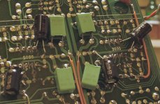
Evening all!
Just remembered to get that pic of the bypass caps sorted. I hope it's fairly clear after editing...
Ignore the green caps: they're fairly pointless bypassing of the main supply caps (1uF).
You can see the relevant caps, which are 33uF/50v: they are the Panasonic FC lovelies and they fit quite snugly under the pcb.
Attachments
Jespr - your Flea boards made today's post, please tell how you find the idea with utmost honesty. All feedback is good 🙂
As an aside - I can't agree the AD8620 sounds thin - then again, we all hear things differently.
It's a funny game really, if you are used to a system that has 'edgy' treble and later hear something that's very refined it can actually sound really dull. I think this is why people occasionaly criticise ESL57s and the like, though having owned serviced pairs they really are *stunningly* natural. What I'm getting at is simply this: often that which is 'right' is not immediately impressive...
Best Regards, Martin
SimontY said:Evening all!
Just remembered to get that pic of the bypass caps sorted. I hope it's fairly clear after editing...
Ignore the green caps: they're fairly pointless bypassing of the main supply caps (1uF).
You can see the relevant caps, which are 33uF/50v: they are the Panasonic FC lovelies and they fit quite snugly under the pcb.
Thanks SimontY
Maybe stupid question, but the - side of the cap goes to ground with the cap connected to + side of the opamp and to the + side goes to ground with the cap connected to the - side of the opamp, correct?
gy21 said:
Thanks SimontY
Maybe stupid question, but the - side of the cap goes to ground with the cap connected to + side of the opamp and to the + side goes to ground with the cap connected to the - side of the opamp, correct?
Hi.
Not a stupid question !
It depends on how you bypass the opamps. 1 cap or 2 .
Simon has used 2 caps - + to gnd. and gnd to -
Hence your possible confusion.
It is also possible to use 1 cap between + and - .
Only criticism - the lead to gnd should be as short as possible to minimise 'ground bounce' which is why smt caps are better - they get closer.
Andy
- Home
- Source & Line
- Digital Source
- Marantz CD63 & CD67 mods list