6h5c said:
Andy,
How's your tubestage going?
Regards,
Ray.
Hi.
Waiting on some components - should have it running at the weekend.
Andy
I have been listening to my HF RF and Servo upgrades over the last two days.
I will say every single part of the music has improved.
It's not like when you change the op amps or when you do the HDAM it's more subtle.
The treble is more controlled, the mid is smoother and the resonance in the bass is a lot better.
I do believe this mod will only truley shine once the op amp hdam regs clock stuff is done first. I think it would be wasted otherwise.
These three mods need to be done on the 63 as all three circuits are connected to each other.
I recommend........
Now roll on servo hf rf reg pcb lol
and valve output
oneday it wil all end
...............
oneday it wil all end
................[/B]
I was thinking overnight that one area we have overlooked so far is the type of plastic that the front panel is made of!
We could have some custom made in carbonfibre composite with copper interwoven to provide a Gaussian screen.
Oh, the vans just arrived with those nice men in white coats....
ooop's
now i've done it
i'am going to have to read this whole thread
I've been looking for another cdp to mod.
already have cd850 (yes the classic)mk1 i've been modding eg clock.opamps mute etc
Am going to do psu, i2s out, etc
just needed spare cdplayer just in case i stuffed it for a while
i just got myself a cd67
very good condition, not very old or used.
sound? not bad, but is totally stock
Has a lot of promise.
Could be an interesting project?
which one can better the easiest and/or overall.
allan
Hi Allan,
The CD67 is a very interesting project indeed. I don't know the CD850, but the TDA1541 DAC is very nice. If you search this forum you will find lots of info on it.
You can find some interesting info on both DAC's in Thorsten's article.
In my CD57 mod's list you will find an overview of lots of mod's on this player. The CD57 uses the same PCB.
You'd better take some time off to digest this thread 😀.
Regards,
Ray.
yeh ray
up to post 120
"Hmm, looks like guano to me...."
I've often said my bro's electric welding looks like pelican Guano to me.
like my soldering used to be🙄
or still is
the cd850 uses decoder saa7310 dig-filter saa7220 dac saa7321
but i like them😀
the cd67 uses decoder saa7372 filter+dac sm7372
just found data sheet for saa7372 has i2s out? future reference!
just a thought about the hdam circuit
how about bypass opamps and use the fet for dac?
similar to pass's xbosoz
or pass's IV output stage?
awpagan said:the cd850 uses decoder saa7310 dig-filter saa7220 dac saa7321
but i like them😀
Hm, I thought it was the 1541....maybe that is MKII?
just found data sheet for saa7372 has i2s out? future reference!
In the CD63 and 67 the oversampling is done in the SM5872 DAC, so the data out of the 7372 is non-os 😀.
just a thought about the hdam circuit
how about bypass opamps and use the fet for dac?
or pass's IV output stage?
Yeah, that could be possible. But you'll have to use some kind of passive filtering. But the HDAM will not combine the signal of both outputs of the DAC.
IV stage is not possible for this DAC, since it has PWM voltage outputs 😀
Ray.
up to post 350 now, very interesting reading
will continue tomorrow
?your 3 pin power plug iec socket, earth or grd point
won't a star earth be useful?
every voltage is relative to earth
if no earth in cdplayer, electrons will find the lowest resistance back to earth.
maybe throught the ground on the output rca's to the amp's earth.
a thought since the earth circuit in the board is all over the place.
and before you say neutral for earth
neutral can be very noisey.
back to reading
custom transformer?
allan
ps hmmmm passive😀
Hi Allan,
The idea to ground the player was born from the fact that I have a tubeamp that is grounded, for obvious safety reasons. I didn't want the ground current to travel through the interlinks shield. So I decided to ground (or "earth") the player and create a second low resistance path and see what happens. With the risk of creating a humming ground-loop, but fortunately the whole setup is mouse-quiet 😀.
I chose to ground the player at the output's ground star-point. If you take a look at the layout you can see all the PSU ground traces go there. The ground layout is not the best in this player, but this seemed like the only sensible place....
Ray.
The custom toroidal
And now for something completely different....
What's the status of our custom tranny project?
Is it just me, or has everybody's enthousiasm regarding this idea cooled down a bit?
Or am I just being impatient 😀? I'd really like this thing to go through.
Michael, you were going for a quote on a 50VA, any news yet?
Regards,
Ray.
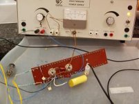
Balanced Tube Output
Hi Folks.
After a short delay ( I broke my soldering station ! ).....
It's going and sounds excellent.
Really good bass, mid and top a bit recessed - need to play around with the filter caps a bit - I used slightly different (higher) values to Thorsten's. Also the amp is on long leads from the cd-p - 12" or so and it's only in mono.
I used 12k anode resistors not dual cascode but I will try later and see if it makes any difference.
NOTE THE VOLTAGE BEING USED !!!!!!!!!!!! 50v
I have taken the B+ down to 20v.
The output drops and distortion starts at this point but from 25v up i cannot hear any difference.
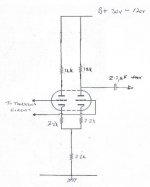
I will post a circuit when I have drawn it.
Andy
Hi Folks.
After a short delay ( I broke my soldering station !
).....It's going and sounds excellent.
Really good bass, mid and top a bit recessed - need to play around with the filter caps a bit - I used slightly different (higher) values to Thorsten's. Also the amp is on long leads from the cd-p - 12" or so and it's only in mono.
I used 12k anode resistors not dual cascode but I will try later and see if it makes any difference.
NOTE THE VOLTAGE BEING USED !!!!!!!!!!!! 50v
I have taken the B+ down to 20v.
The output drops and distortion starts at this point but from 25v up i cannot hear any difference.
I will post a circuit when I have drawn it.
Andy
Attachments
Excellent dude!
The tubes are starting to be common practice in this thread 😀.
I'm about to order some parts for it and build the passive filter part on the players PCB.
Wow, 50 volts is low! This can be done with a standard 2x24V tranny. I did notice the circuit goes on for a long time when I switch-off my power supply. What tubes did you use?
Do you have a (too) high output signal?
Lose the 2k2 resistors and try the CCS FET in the tail. It will bring balance in the circuit, cuz the resistor is not much of a constant current.
Regards,
Ray.
Wow, 50 volts is low! This can be done with a standard 2x24V tranny. I did notice the circuit goes on for a long time when I switch-off my power supply.
Yes, it is low. It does not make an audible difference if I increase it to 100v so I am redesigning the psu to use a 20-0-20 tx I have. ( Maybe the redundant windings on the existing Tx ?? )It should fit on the board with the amp.
I am putting all the stuff on the board and using links to the Marantz PCB ( DAC output ).
What tubes did you use?
I've used E88CC and ECC88. I will try the small valves soon! (single 6.3v heater )
Do you have a (too) high output signal?
Yep. It does seem on the high side. It overloaded the radio input to the small amp I first tried it out with but was ok (low) on the tape. (it's an old Armstrong of early '70s)
Lose the 2k2 resistors and try the CCS FET in the tail. It will bring balance in the circuit, cuz the resistor is not much of a constant current.
Balance is not bad according to my meter but it's on the list for trying tomorrow.
Now that it has been running for some hours, it seems to have 'run in' and now sounds better.
'She who must be obeyed' says it sounds really good! I realised that the lack of prescence etc was due to the fact that it is MONO!!! and 1 channel only !!!!
I have just bought a Marantz cd53 ( no HDAM to remove ) for future experiments!!!
Andy
poynton said:'She who must be obeyed'
Wow, do you have your mother-in-law living with you 😱? 😀
Cool!
When I receive my parts i'm going to try it on 50V too. I have two PCC88's here that I can use. It has a bit high mu for this application, but it is better suited for low-voltage use.
I'm curious how the small valves will do.
Did you measure any noise residue at the output that I experienced earlier?
Ray.
low voltage for tubes
this may give some ideas
http://headwize.com/ubb/showpage.php?fnum=3&tid=5395&fpage=2
allan
post 17
this may give some ideas
http://headwize.com/ubb/showpage.php?fnum=3&tid=5395&fpage=2
allan
post 17
Different heater voltage but should work (see awpagan's post). An attenuator may need to be used (!!!!) if the stage gain is too high . Try ECC82/81 , I have loads - want some? I am also going to try some new Russian tubes, 6N3P. The pin layout is good for pcb making.6h5c said:
............ I have two PCC88's here that I can use. It has a bit high mu for this application, but it is better suited for low-voltage use.....................
I'm curious how the small valves will do.
Me too. I note on the site below that using JAN6111WA pencil tubes is mentioned.
Did you measure any noise residue at the output that I experienced earlier?Ray.
Not yet. The amp I'm using puts out loads of hiss anyway but using the cd-p did not seem to increase it any.
awpagan said:low voltage for tubes
this may give some ideas
http://headwize.com/ubb/showpage.php?fnum=3&tid=5395&fpage=2
allan
post 17
Thanks. I had already looked at Headwize for some ideas - very useful.
Andy
Hi Allan,
Thanks for the link! I didn't think of the headphone-guys. They are used to using tubes at low voltages for a long time 😀.
Your earlier remark about the HDAM circuit got me thinking (again...).
Maybe it can be changed as you said, into a discrete buffer without any feedback, to buffer Thorstens filter circuit. I'm going to look into that and do some experiments.
I got some inspiration when I found this circuit again at Ultranalog.
The differential input stage and current source are already there in the HDAM.
Regards,
Ray.
Attachments
6h5c said:...............Lose the 2k2 resistors and try the CCS FET in the tail. It will bring balance in the circuit, cuz the resistor is not much of a constant current............
Ray.
Did you use a 2SK170 for the CCS and did you have to select it for the 4mA? I have a lot of 2N5484 - I suppose i can use them?
Andy
- Home
- Source & Line
- Digital Source
- Marantz CD63 & CD67 mods list