Either far apart, or if the signal travels through a particularly noisy/busy part of the circuit perhaps?
When building guitar amplifiers I've found the use of coax to be critical; even runs of two inches can make a good contribution to reduction of noise.
Digital and audio signals are entirely two different things. Audio signals can pick up noise and be affected by interference more easily.
Digital and audio signals are entirely two different things. Audio signals can pick up noise and be affected by interference more easily.
Ah good point

The HF signal from the laser IC is high frequency analogue so I'm going to coax that I think
The HF signal from the laser IC is high frequency analogue so I'm going to coax that I think
Please keep us posted of your findings 😉 Hope you can hear some improvements.
Please keep us posted of your findings 😉 Hope you can hear some improvements.
Sorry I know I've joined the thread about a decade too late 🙁
I'm looking in to affordable regulators at the moment - LT1086. I'd like to add one to the driver on the transport PCB and the. As many other chips as possible to separate all the power signals. I have 3 5V super regs to use but can't decide which chips to prioritise.
Optimising the power supplies of each chip the. Using shielded cables for all the analogue signals is all that I want to do I think (after I install a seconds TX for the servo chips)
I would choose dac digital, dac analog and the decoder.I have 3 5V super regs to use but can't decide which chips to prioritise
Also,add a separate regulator to the main display chip. Only needs to be something cheap like a 7805. this chip doesn't need a posh, quiet supply, but it makes a lot of digital noise into the supply, so it's good to separate it from the rest with its own regulator and remove the noise from the rest of the city circuit
Thanks for this. I was thinking of using my 3 super regs for the most critical chips and then LT1086's with a 10uF tantalum decoupler on each leg (and perhaps a reservoir cap too) for each of the remaining chips
The HF signal from the laser IC is high frequency analogue so I'm going to coax that I think
It has been done before 🙂
Quick sanity check:
Adding extra regs. In ray's notes of a separate reg for for Dac analogue he mentions adding a "small" cap between the reg and the dac. Does that become a reservoir cap then; charged by the reg, discharged by the dac when it draws current? How small is small? I only ask because the other regs on the board seem to have caps from output to ground.
What happens if you use a big cap here, like 470uF or even 1,000uF?
Perhaps I didn't phrase that very well.
If I want an additional reservoir cap with an added reg, should it go in series with the output leg or in parallel (to ground)?
Is it worth adding 100n SMD decouplers between the legs too to filter out noise?
If I want an additional reservoir cap with an added reg, should it go in series with the output leg or in parallel (to ground)?
Is it worth adding 100n SMD decouplers between the legs too to filter out noise?
...sry for this kind of offtopic. but in which thread page can I find the latest modlist as pdf ? this is 2045 ....quite long and as far as I know there is no proper filesearch for this forum.
thanks for your help in advance
best regards
thanks for your help in advance
best regards
It should be in parallel (decoupling)Perhaps I didn't phrase that very well.
If I want an additional reservoir cap with an added reg, should it go in series with the output leg or in parallel (to ground)?
Is it worth adding 100n SMD decouplers between the legs too to filter out noise?
As to what's suitable for extra caps, it kind of depends what regulators you're using and how close you have them to the thing requiring the powering (closer is better)
Extra smd caps are in theory to cater for high frequencies, but modern caps are much better at coping with high frequencies, and these frequencies tend to be above the audible spectrum, so the benefits if any will be negligible imo
It should be in parallel (decoupling)
As to what's suitable for extra caps, it kind of depends what regulators you're using and how close you have them to the thing requiring the powering (closer is better)
Extra smd caps are in theory to cater for high frequencies, but modern caps are much better at coping with high frequencies, and these frequencies tend to be above the audible spectrum, so the benefits if any will be negligible imo
I thought so. I've chosen LT1086-5 regs (fixed 5V) and a 150u rubicon cap on output (taken from data sheet). On my super reg feeding Dac analogue I've chosen a 470u Panasonic FC. The super regs can only put out up to 600mA I think where as the LT 1086 can do 1.5A!
I had some 100n caps left over from my shopping list of parts for Ray's PDF mod list so I've just used them to be safe than sorry (not on the super regs though obviously).
Do you know the minimum load for those regs to regulate effectively? You may find you need to put additional load resistors across the outputs to get them to work nicely. I don't recall exactly as it's been a while, but I'd be surprised if the load on the individual regs is more than 100mA when you separate everything up
Do you know the minimum load for those regs to regulate effectively? You may find you need to put additional load resistors across the outputs to get them to work nicely. I don't recall exactly as it's been a while, but I'd be surprised if the load on the individual regs is more than 100mA when you separate everything up
I can't find anything in the datasheet regarding minimum loads but it mentions it can supply currents as low as 5mA whilst maintaining stability.
Hi Higlander
I've just been looking at this image you posted a while ago. I've been really busy with work, but have finally found time to work on this replay problem.
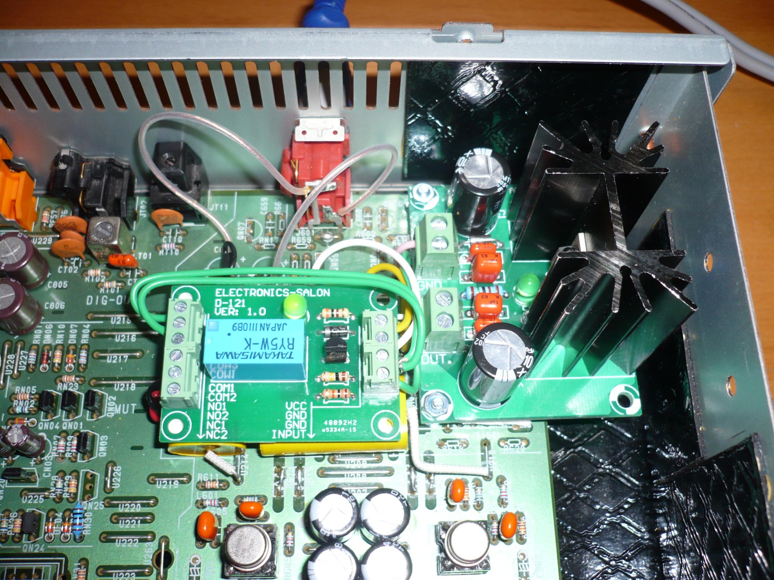
I've decided to bypass the HDAM (on my CD67) and wire the RCAs through the relay. I have also bought some caps and tested the new sockets without the relay. Works and sounds great! Now the wiring of the relay. As ray has helped me with - I've wired mine incorrectly and I'm looking at yours to help guide my work.
COM 1 and 2 - go to ground (you've wired this across) to GND on your relay.
NC 1 and 2 - are the red and black twisted wires the coax wires leading from the RCAs or are these connected to the other end of the caps on the signal path? I can see the caps are connected R611 and R608 (on my CD67) - what about the other ends.
VCC on mine connects to the collector of QN02 (12v) (your relay is 5V)
INPUT comes from the based of QN07/8
How I wire up that signal to the RCAs and the GND connections seems to the the issue - at the moment it switches correctly when the CD plays, but switching off the CD player (and the relay) still results in static/crackling from the outputs.
Any (fairly non technical) advice on how you wired yours, or even a shot underneath your replay would help!
Thanks,
Peter
I've just been looking at this image you posted a while ago. I've been really busy with work, but have finally found time to work on this replay problem.
I've decided to bypass the HDAM (on my CD67) and wire the RCAs through the relay. I have also bought some caps and tested the new sockets without the relay. Works and sounds great! Now the wiring of the relay. As ray has helped me with - I've wired mine incorrectly and I'm looking at yours to help guide my work.
COM 1 and 2 - go to ground (you've wired this across) to GND on your relay.
NC 1 and 2 - are the red and black twisted wires the coax wires leading from the RCAs or are these connected to the other end of the caps on the signal path? I can see the caps are connected R611 and R608 (on my CD67) - what about the other ends.
VCC on mine connects to the collector of QN02 (12v) (your relay is 5V)
INPUT comes from the based of QN07/8
How I wire up that signal to the RCAs and the GND connections seems to the the issue - at the moment it switches correctly when the CD plays, but switching off the CD player (and the relay) still results in static/crackling from the outputs.
Any (fairly non technical) advice on how you wired yours, or even a shot underneath your replay would help!
Thanks,
Peter
Hi Higlander
I've just been looking at this image you posted a while ago. I've been really busy with work, but have finally found time to work on this replay problem.
I've decided to bypass the HDAM (on my CD67) and wire the RCAs through the relay. I have also bought some caps and tested the new sockets without the relay. Works and sounds great! Now the wiring of the relay. As ray has helped me with - I've wired mine incorrectly and I'm looking at yours to help guide my work.
COM 1 and 2 - go to ground (you've wired this across) to GND on your relay.
NC 1 and 2 - are the red and black twisted wires the coax wires leading from the RCAs or are these connected to the other end of the caps on the signal path? I can see the caps are connected R611 and R608 (on my CD67) - what about the other ends.
VCC on mine connects to the collector of QN02 (12v) (your relay is 5V)
INPUT comes from the based of QN07/8
How I wire up that signal to the RCAs and the GND connections seems to the the issue - at the moment it switches correctly when the CD plays, but switching off the CD player (and the relay) still results in static/crackling from the outputs.
Any (fairly non technical) advice on how you wired yours, or even a shot underneath your replay would help!
Thanks,
Peter
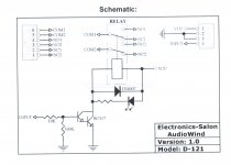
@station: Please see the diagrams which explain better than a thousand words.
Attachments
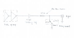

The first hand written one is exactly what I'm looking for.
Thanks so much - that now makes sense!
Thanks so much - that now makes sense!
The first hand written one is exactly what I'm looking for.
Thanks so much - that now makes sense!
You are welcomed. Do update us when you have successfully put in the muting circuit.
It should be in parallel (decoupling)
As to what's suitable for extra caps, it kind of depends what regulators you're using and how close you have them to the thing requiring the powering (closer is better)
Extra smd caps are in theory to cater for high frequencies, but modern caps are much better at coping with high frequencies, and these frequencies tend to be above the audible spectrum, so the benefits if any will be negligible imo
I've played around in this area quite a bit and I've settled on 470uF audio grade decoupling caps as close to the load as possible with no bypass caps of any kind. I haven't tried the Sanyo OSCONs yet, but from what I've read it sounds like they're the best available for digital supplies. I've only really experimented with Black Gates, Elnas and Mundorfs in my player. I ended up with BG FK on analogue supplies and NX on digital as an approach, but only a few positions jumped out as being really sensitive or effective. The main 'rolling' I've done has been with DAC analogue, op-amps, output tx post-reg and decoder. I've tried bypassing with 100n WIMA caps in these sensitive areas a few times now and the result has been total garbage.
- Home
- Source & Line
- Digital Source
- Marantz CD63 & CD67 mods list