The wires are enamelled and that coating takes a lot of heat to burn off, but it is possible. It can also be scraped off with a sharp knife blade.
Problem solved, it's c854.resolder & display is on again...
OK, my display is back again now - it was a detached pad at c854. Now I have an error code to look at - Error 10.
Getting there!
Edit: In Service Mode 3, the disc spins in alternate directions. Very odd.
Last edited:
I've fixed it at last! It was another (invisibly) detached pad at c505.
For future reference, the symptoms were:
- Radial error
- Disc spins one way, then the other on power up
- In P03, disc speed oscillates erratically forwards and backwards
Anyway, all fixed now and sounding good. What a palaver. Thanks for the moral support. I'm going to leave the screws in until those Tentlabs XOs arrive.

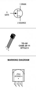
Hi chaps finally getting round to building a Kwak clock 7 (attached circuit) for my 67OSE however I wanted to double check orientation of Q1 (mid left of diagram) with you guys, I assume the Source is terminated to L1 and Drain to R1????
Tom
Tom
Attachments
Last edited:
Ok thanks so from that Drain (collector) to L1 and Source (emitter)to R1?
Regards
Tom
Sounds correct!

Thanks as per circuit then, I wasn't sure going by the names thinking source should connected to teh source rather than being the source.
(had all the parts since last May only started building it last night)
One more question gnd on the circuit is that chassis gnd or is there an 0V/gnd on the player board to connect to?
Appreciated
Tom
(had all the parts since last May only started building it last night)
One more question gnd on the circuit is that chassis gnd or is there an 0V/gnd on the player board to connect to?
Appreciated
Tom
I've used the top screen as gnd without issue previously!!!!!
However I'd pick gnd up from the supply smoother on the 5v supply. It's sort of the natural point for a star earth. Make sure you only have 1 gnd connection onto the clock pcb.
However I'd pick gnd up from the supply smoother on the 5v supply. It's sort of the natural point for a star earth. Make sure you only have 1 gnd connection onto the clock pcb.
The 5v reg is the 7805 near the middle of the board with the heat sink on it. The pin order is In, Ground, Out. The supply smoother is the big cap right next to it, connected to the In and Ground traces. The ground wire would go directly to the pin of the cap connected to the ground. That's also the pin marked with the stripe running down the side of the cap.
Thanks chaps, hopefully time permitting will have it all done by the weekend.
much appreciated.
Tom
much appreciated.
Tom
Hi
Would like to use 63KI as transport
Mod done so far are: tent clock 16.934Mhz, Alwsr 5V regulator and some caps changed for PS
Is the servo section important ? Thinking of replacing the 8.4 Mhz clock.
The power supply 5V is regulated by 7805, original
Please recommend parts to mod to make a good transport
Sorry if these have been discussed. Quite impossible to read the longest thread
Thanks
The main things to do here are:-
1, Clock the servo with s dedicated low jitter clock
1, fit large 22,000uF low ESR smoothing caps on the +/- rails
1, regulate the 3 driver IC's and provide quality PSU rail decoupling
1, build a large 100+va PSU to drive this section
Yes its ALL very important!!!
1, Clock the servo with s dedicated low jitter clock
1, fit large 22,000uF low ESR smoothing caps on the +/- rails
1, regulate the 3 driver IC's and provide quality PSU rail decoupling
1, build a large 100+va PSU to drive this section
Yes its ALL very important!!!
Thanks UV101
"build a large 100+va PSU to drive this section" you mean the 5V, ie from 7805 reg onwards?
Are the 3 driver ICs already supplied with regulated ps?
Thanks for assisting in my mod
"build a large 100+va PSU to drive this section" you mean the 5V, ie from 7805 reg onwards?
Are the 3 driver ICs already supplied with regulated ps?
Thanks for assisting in my mod
The drivers are 12v, unregulated. I can definitely recommend the "Search this thread" feature if you don't want to read the whole thing. It's helped me a lot. There's a lot of information in here and it'd be a shame to make Ian have to repeat it all 🙂
Brent has written a useful step-by-step upgrade guide here: Marantz CD63 upgrade guide. It starts with the servo section.
Brent has written a useful step-by-step upgrade guide here: Marantz CD63 upgrade guide. It starts with the servo section.
Lol thanks Ben 😉
If you dont already have the service manual, go to post 1 by Ray and follow the link to his homepage. You can get the manual there.
Basically the driver ic's run from the unregulated side of the +5v regulator and the equivalent for neg rails ( there is no neg reg). Replacing the main smoothing caps with v large 22,000uf low esr caps hear make a massive difference. Also you can use the unregulated rail to supply regulators connected at each driver ic pin. With respect to the transformer, that would be when you build a dedicated psu for the driver ic's running at +/-12v regulated and supply them from the new psu. I'll see if I can find the relevant posts later 😉
- Home
- Source & Line
- Digital Source
- Marantz CD63 & CD67 mods list