RCruz said:I still have a small issue..... The remote only works if pointed at less than one inch from the sensor in the CDP.
I do not know what started this but it is like that for a couple of month now.
Try an electrolytic (10...47u/16V) in parallel with CY01 on the front panel PCB, worked for me. I noticed the IR receiver somehow becomes less sensitive when RY11 is replaced by an inductor.
Ray
6h5c said:
Try an electrolytic (10...47u/16V) in parallel with CY01 on the front panel PCB, worked for me. I noticed the IR receiver somehow becomes less sensitive when RY11 is replaced by an inductor.
Ray
Ray lurks and emerges with the answers!


Re: Ricardo the TX behind the mechanism?
No problem, it will be posted tomorrow
Drill the back panel and use a nut and bolt for the tx. Most txs come with insulation pads
Brent
magilla said:
Also a public thanks to Brent for cleaning up my C1.
No problem, it will be posted tomorrow
Drill the back panel and use a nut and bolt for the tx. Most txs come with insulation pads
Brent
Thank you Ray6h5c said:
Try an electrolytic (10...47u/16V) in parallel with CY01 on the front panel PCB, worked for me. I noticed the IR receiver somehow becomes less sensitive when RY11 is replaced by an inductor.
Even with new batteries, the remote only works at about 15cm from the CDP.
I will surely try this cap in CY01....I will solder it from the back of the pcb so I do not need to remove it. .....

Regards
Ricardo
6h5c said:
Try an electrolytic (10...47u/16V) in parallel with CY01 on the front panel PCB, worked for me. I noticed the IR receiver somehow becomes less sensitive when RY11 is replaced by an inductor.
Can I use a 10uF 35v Ruby ZL ?
The other option is a 120uF Pana ... too big maybe.
Ricardo
Just use one of the original ones, you must have a bunch of them after having upgraded the whole machine.
Just grab what comes handy.
Just grab what comes handy.
Also check RY11 for resistance. I've seen these go high resistance before, usually after the ribbon not being inserted correctly and shorting 5v to gnd. RY11 should be 4.7 ohm.
If these things mentioned in the thread do not not cure the problem then you may have a duff connector (or you are holding the remote the wrong way round 😀)
Brent
If these things mentioned in the thread do not not cure the problem then you may have a duff connector (or you are holding the remote the wrong way round 😀)
Brent
output stage again...
another thing about output stage, this time Ray's discreete.
how about substituting R11 with a pot ?
couldn't one adjust DC offset this way and get rid of the output cap ??
greetings,
Pawel
i am going to fit discreete output, I am just curious, the cost will be rather small for me, I just need some Rs and low-pass filter components 🙂
Re: output stage again...
I have been meaning to ask this for a while. It would be nice to do away with the cap altogether.
Lee.
pzogal said:another thing about output stage, this time Ray's discreete.
how about substituting R11 with a pot ?
couldn't one adjust DC offset this way and get rid of the output cap ??
greetings,
Pawel
I have been meaning to ask this for a while. It would be nice to do away with the cap altogether.
Lee.
rowemeister said:....(or you are holding the remote the wrong way round 😀)
Brent

Re: output stage again...
Nope, not possible this way. The only result of a pot is that there will be more or less current running through the output transistor and the pot, but the voltage will not change much.
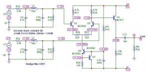
Take a good look at the circuit. Where does the voltage across R11 come from? T5 acts as an emitter-follower, so any voltage at the base, will appear on the emitter, minus Ube (= ~0.7V). So the voltage originates at R6/T2. To make the output voltage exactly 0V, the voltage at that point has to be about 0.7V, and thus 11.3V has to be dropped by R6, because the supply is +12V. At 4k7, this means a current of approx. 2.4mA has to flow through it, instead of 1mA now.
So maybe the current setting resistor can be made variable. Let's see what happens when you increase the current. The collectors of the differential amp will be at ~0.7V at some point and the voltage at the output should drop to zero. You have to lower R11 to 1k2 to keep 10mA running through the output transistor.
BUT... now there is no voltage left for both transistors to work on! If you want to have an output that swings to both positive and negative sides, you need HEADROOM, or in this case some voltage left ACROSS the transistor so it can swing up and down. The voltage at both bases of the differential transistors is about 1.2V, that's the DC voltage coming from the passive filter. The emitters will be 0.7V lower, so about 0.5V. With 0.7V on the collector, that makes only 1.2V Uce! That's not enough to produce a decent output signal.
Here's a pic of the circuit with the correct voltages included. Oh, how I love my simulation program. 😀
This concludes the analog electronics lesson for today!
Ray
pzogal said:another thing about output stage, this time Ray's discreete.
how about substituting R11 with a pot ?
couldn't one adjust DC offset this way and get rid of the output cap ??
greetings,
Pawel
Nope, not possible this way. The only result of a pot is that there will be more or less current running through the output transistor and the pot, but the voltage will not change much.
Take a good look at the circuit. Where does the voltage across R11 come from? T5 acts as an emitter-follower, so any voltage at the base, will appear on the emitter, minus Ube (= ~0.7V). So the voltage originates at R6/T2. To make the output voltage exactly 0V, the voltage at that point has to be about 0.7V, and thus 11.3V has to be dropped by R6, because the supply is +12V. At 4k7, this means a current of approx. 2.4mA has to flow through it, instead of 1mA now.
So maybe the current setting resistor can be made variable. Let's see what happens when you increase the current. The collectors of the differential amp will be at ~0.7V at some point and the voltage at the output should drop to zero. You have to lower R11 to 1k2 to keep 10mA running through the output transistor.
BUT... now there is no voltage left for both transistors to work on! If you want to have an output that swings to both positive and negative sides, you need HEADROOM, or in this case some voltage left ACROSS the transistor so it can swing up and down. The voltage at both bases of the differential transistors is about 1.2V, that's the DC voltage coming from the passive filter. The emitters will be 0.7V lower, so about 0.5V. With 0.7V on the collector, that makes only 1.2V Uce! That's not enough to produce a decent output signal.
Here's a pic of the circuit with the correct voltages included. Oh, how I love my simulation program. 😀
This concludes the analog electronics lesson for today!
Ray
Attachments
Re: Re: output stage again...
Excellent and informative reply Ray, especially for noobs like me! Thank you.
Lee.
6h5c said:
This concludes the analog electronics lesson for today!
Ray
Excellent and informative reply Ray, especially for noobs like me! Thank you.
Lee.
Thanks, avr.
I decided to post the picture later, but the version you posted can't be simulated, as it is optimized for publishing. I didn't want to draw another one...
Ray
I decided to post the picture later, but the version you posted can't be simulated, as it is optimized for publishing. I didn't want to draw another one...
Ray
6h5c said:Try an electrolytic (10...47u/16V) in parallel with CY01 on the front panel PCB, worked for me. I noticed the IR receiver somehow becomes less sensitive when RY11 is replaced by an inductor.
I used a 10uF 35v (saved for the ocasion).rowemeister said:
If these things mentioned in the thread do not not cure the problem then you may have a duff connector (or you are holding the remote the wrong way round 😀)
Problem fixed...... I can remote from afar again....
Note: I did not try it backwards yet 😀
Ricardo
Excellent news. It makes little difference where I point my remote, my player's still 30 miles away LOL


SimontY said:Excellent news. It makes little difference where I point my remote, my player's still 30 miles away LOL
As I said before, I believe you are very lucky Simon... You can even drive your CDP directly to the Doctor.
Imagine what would be my situation... having to dismantle everything, pack it carefully and send it by air mail...

What type of output have you on your machine ?
With all this detail, I believe I need discrete outputs... but good ones are so expensive.
Ricardo
- Home
- Source & Line
- Digital Source
- Marantz CD63 & CD67 mods list