I agree, SPower on dac analog was one of the best mods I did. I found it a fair bit better than the Invisus, which I've stuck on dac digital.
Also one of the really good mods was to supply the chip under the transport/laser with its own psu and two 5v regs. This gave a pretty big boost. Obviously, only applies to CD67.
Has anyone else done this on a '67?
Cheers, Lee.
Also one of the really good mods was to supply the chip under the transport/laser with its own psu and two 5v regs. This gave a pretty big boost. Obviously, only applies to CD67.
Has anyone else done this on a '67?
Cheers, Lee.
Lee. I have a dedicated 5V to the pcb under my mech, with it being the 63 mine is transistor based, and yes there was an improvement. Delicate sounds like cymbols become clearer and less like white noise.
Brent
Brent
RCruz said:Thanks
I will go for the SPower on dac analog first.
You won't regret it 😉
Also the ground plane is the copper that covers the top of the pcb. The little wire links that have a solder blob on them are linking it to the relevent part of the circuit.
Brent
Hi Brentrowemeister said:
You won't regret it 😉
Also the ground plane is the copper that covers the top of the pcb. The little wire links that have a solder blob on them are linking it to the relevent part of the circuit.
Please excuse my ignorance... What is the use for the grounplane ?
Is it for screening ?
Regards
Ricardo
RCruz said:
Hi Brent
Please excuse my ignorance... What is the use for the grounplane ?
Is it for screening ?
Regards
Ricardo
Here you go.
http://www.sigcon.com/Pubs/news/7_02.htm#note3
🙂
avr300 said:
BTW, I think it has been covered before - in 2006. What was the designers thinking about when they designed the ground and groundplane ?
There's a starground for digital (under C814) and one for analog (at RCA), but they mess up in the groundplane in top of the PCB. I have just separated agnd and dgnd, easy to do when you have enough power supplies and a discreet board. The DAC is the separation point.
Hiavr300 said:
I already read the notice and am now aware of the potential issues related with mixing Digital and Analog signals via groundplane.
Any reason why Marantz built the pcb like this ? I can identify three star gnd (1 analog, 1 digital and one below the outputs).
They should link together in only one point to avoid ground loops... The groundplane seems to be connected in several points and this can create problems in the analog circuits.
Can you please detail your modd ?
I have a dedicated power supply for the opamps... Can I separate the gnd easily ?
I already have a central star gnd that I am using to ground the regs of the servo.
Best regards
Ricardo
RCruz said:
Hi
I already read the notice and am now aware of the potential issues related with mixing Digital and Analog signals via groundplane.
Any reason why Marantz built the pcb like this ? I can identify three star gnd (1 analog, 1 digital and one below the outputs).
They should link together in only one point to avoid ground loops... The groundplane seems to be connected in several points and this can create problems in the analog circuits.
Can you please detail your modd ?
I have a dedicated power supply for the opamps... Can I separate the gnd easily ?
I already have a central star gnd that I am using to ground the regs of the servo.
Best regards
Ricardo
No, I can tell why the layout is done this way, but it's surely not following the textbook.
I would concentrate on mainly two, the analog under the RCA, and "the rest" which are digital. The DAC is an obviously and possible separation point.
If you look at this picture, you can see, that the agnd pins from the DAC links nicely to the analog starground.
Attachments
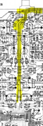
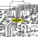
If you do follow the agnd starground, it's possible to remove U201 which connects the analog starground to the top plane.
You must check yourself, if this is the only connection.
Your analog PSU must conncect it's gnd to this agnd starground.
That's why I says, it's much more easy to do, when you have a separate outputboard. My agnd is mainly my gnd on my discrete board.
Ohh, and pls. do remember, the standard RCA connector connects the agnd to the chassis. I can't remember whether the chassis is connected elsewhere in the standard machine, check with a DMM.
Attachments
Thank you again 😉
I will be searching for other points where the agnd links to the top plane and get back latter.
My analog psu uses the gnd near C803 / 804 that are still functional.
This star gnd is also a analog gnd right ?
Ricardo
I will be searching for other points where the agnd links to the top plane and get back latter.
My analog psu uses the gnd near C803 / 804 that are still functional.
This star gnd is also a analog gnd right ?
Ricardo

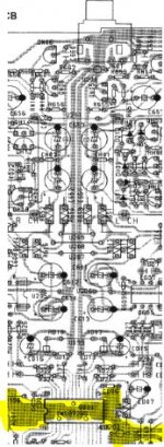
Following the digital star gnd near Q811 +5vreg, I can see it links to the servo and drivers below, to the analog psu between c803 c804, but also to the analog star near U201.
From here, the lines go to the analog dac gnds but also to the digital ones (using independent lines).
So analog and digital gnds are all linked together.
Should I try to isolate the agnd from the dac and opamps from the star near U201 ?
Ricardo
From here, the lines go to the analog dac gnds but also to the digital ones (using independent lines).
So analog and digital gnds are all linked together.
Should I try to isolate the agnd from the dac and opamps from the star near U201 ?
Ricardo
Ray's Discrete Output Stage
Since reading this whole thread last month, took awhile to read all 380 odd pages, I am not interested in constructing the discrete output stage Ray has designed. The design shows 3 2SK170BL jfet's in each channel. These are a little hard to come by. Is there any alternative that would work well in this design?
Oh, and btw, what a great thread this is. I have SA-8260, much like the SA-8400, and I've found much information here that has been very helpful in my modifications.
Re: Ray's Discrete Output Stage
Hello. There is a transistor version which uses BC550's and 2sc2240. But if you have a cd63/67 with hdam, I think all of the 2sk170's are present in that circuit, so you can just pinch them from there.
Oh, and I have a few 2sk170's, I could send you some if you like, just mail me
Regards, Lee.
stvnharr said:Since reading this whole thread last month, took awhile to read all 380 odd pages, I am not interested in constructing the discrete output stage Ray has designed. The design shows 3 2SK170BL jfet's in each channel. These are a little hard to come by. Is there any alternative that would work well in this design?
Oh, and btw, what a great thread this is. I have SA-8260, much like the SA-8400, and I've found much information here that has been very helpful in my modifications.
Hello. There is a transistor version which uses BC550's and 2sc2240. But if you have a cd63/67 with hdam, I think all of the 2sk170's are present in that circuit, so you can just pinch them from there.
Oh, and I have a few 2sk170's, I could send you some if you like, just mail me
Regards, Lee.
Attachments
Re: Re: Ray's Discrete Output Stage
Lee,
Thanks for that. My 8260 multichannel board has some 2SK170's on it, so I suppose I could just use those since I don't use the board.
I just finished with a whole bunch of mods, so next project may be the output stage. But maybe not for awhile.
Steve
Thomo said:
Hello. There is a transistor version which uses BC550's and 2sc2240. But if you have a cd63/67 with hdam, I think all of the 2sk170's are present in that circuit, so you can just pinch them from there.
Oh, and I have a few 2sk170's, I could send you some if you like, just mail me
Regards, Lee.
Lee,
Thanks for that. My 8260 multichannel board has some 2SK170's on it, so I suppose I could just use those since I don't use the board.
I just finished with a whole bunch of mods, so next project may be the output stage. But maybe not for awhile.
Steve
RCruz said:Following the digital star gnd near Q811 +5vreg, I can see it links to the servo and drivers below, to the analog psu between c803 c804, but also to the analog star near U201.
From here, the lines go to the analog dac gnds but also to the digital ones (using independent lines).
So analog and digital gnds are all linked together.
Should I try to isolate the agnd from the dac and opamps from the star near U201 ?
Ricardo
Yes, it's a mess.
You could try to isolate the agnd, the star near u201 from the rest. This should give you a clean agnd including agnd for the DAC, (pin 19 and 24), gnd for the OPAMP's, gnd for headphone (?, I don't have this in my box anymore) but remember, the DAC has analog power lines on pin 17,21,23,26 (combined in u200) that's reffering to agnd. I'm supplying this from a separate PSU incl. tranny, if you don't have this, take care of that gnd reference.
Don't do anything that you sure about. 😉
avr300 said:
Yes, it's a mess.
You could try to isolate the agnd, the star near u201 from the rest. This should give you a clean agnd including agnd for the DAC, (pin 19 and 24), gnd for the OPAMP's, gnd for headphone (?, I don't have this in my box anymore) but remember, the DAC has analog power lines on pin 17,21,22,26 (combined in u200) that's reffering to agnd. I'm supplying this from a separate PSU incl. tranny, if you don't have this, take care of that gnd reference.
Don't do anything that you sure about. 😉
So I should feed the analog dac and opamps via a separate psu.
This psu can use a reference gnd linked to my "floating" star gnd.
Is this feasible ?
Ricardo
New analog psu for the dac
Hi
Actually I know I need to place a new sreg on the analog dac... (I need to make the sound more coherent)
At he same time I am thinking about separating agnd from dgnd as much as possible.
Before the sreg arrives (I´m now saving some €€€ for next month) I need to prepare it´s PSU.
As I am not using the 17.6v windings of the stock tx (because I have a dedicated tx for the opamps) I wonder if I can I use one of these windings to power the sreg for the analog dac ?
If so, what would be the correct pins of the tx ?
As usual, all your comments will be determinant in this new mod.
Regards
Ricardo
- Home
- Source & Line
- Digital Source
- Marantz CD63 & CD67 mods list