Re: OFF TOPIC - schroeder diffuser
Hi Simon,
That looks very nice too, I have similar this one (70 cm x 180 cm) and I put in the center position (behind audio's rack).
Unfortunately, the rear wall have distance 400 cm from 'sweat spot', so can I put a diffuser behind of 'sweat spot' position ? any suggestion ?
Regards
aquar
SimontY said:Sorry this is off-topic, but if anyone is interested in what was for me a very very important upgrade, have a look at this. It's a diffuser built on the maths of quadratic residues. I can whole-heartedly recommend F. Alton Everest's "Master Handbook of Acoustics" for anyone wishing to make their room sound less rubbish.
Hi Simon,
That looks very nice too, I have similar this one (70 cm x 180 cm) and I put in the center position (behind audio's rack).
Unfortunately, the rear wall have distance 400 cm from 'sweat spot', so can I put a diffuser behind of 'sweat spot' position ? any suggestion ?
Regards
aquar
6h5c said:Which zener values did you use?
Ray [/B]
Hi Ray,
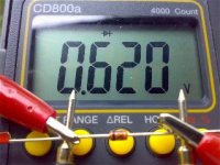
3.3 V, when I hook up with DMM actually 0.6 V

First, in the adj pin I put green led seri with zener, DMM meter read 4.3 V .........so I added zener again (zener-zener-LED) and DMM meter read 4.94 V.......is that right ?
Regards
aquar
Attachments
Re: Re: OFF TOPIC - schroeder diffuser
Thanks, lol. The rear reflections seemed the most troublesome for me.
Simon
6h5c said:
Hey, that looks vey nice Simon. I happen to have some reflections on the left side, but I doubt I will ever get such thing into my livingroom, low WAF, you know... Maybe if John comes with it, depends on where the hairy part is...😀
Ray
Thanks, lol. The rear reflections seemed the most troublesome for me.
Simon
Re: Re: OFF TOPIC - schroeder diffuser
Hi Aquar,
Firstly, I think it's good that you've put a diffuser between your speakers, I'd imagine that helps things a lot.
Secondly, if your rear wall is 4 metres away from your listening position it's probably not a huge problem. But if you can, try experimenting with a diffuser or some sort of furniture/objects that will do a similar, if less effective, job.
Simon
aquar said:
Hi Simon,
That looks very nice too, I have similar this one (70 cm x 180 cm) and I put in the center position (behind audio's rack).
Unfortunately, the rear wall have distance 400 cm from 'sweet spot', so can I put a diffuser behind of 'sweat spot' position ? any suggestion ?
Regards
aquar
Hi Aquar,
Firstly, I think it's good that you've put a diffuser between your speakers, I'd imagine that helps things a lot.
Secondly, if your rear wall is 4 metres away from your listening position it's probably not a huge problem. But if you can, try experimenting with a diffuser or some sort of furniture/objects that will do a similar, if less effective, job.
Simon
DC offset
Hi everyone,
I'm kinda new here and as I happened to get my hands on a CD63 mkII KI I just had to try out some of the things mentioned here. I did the some bypassing of the dac chip as on the acoustica site, added a simple 5V regulator to the dac chip pin 27, switched the opamps for LM4562s which was a big upgrade and bypassed the HDAM and a few more minor things.
Now it sounds very nice indeed, however it sounded even better with the DC-blocking caps at the output bypassed(4 Elna 220uF Silmics), especially the bass got a lot better. The dc-offset was around 30-40mV though which I thought was a little too high, or is it? My amp is a NAD C320BEE. Does it have any protection against incoming dc? What have you done to the DC-caps or what would you suggest I do?
Re: DC offset
I'd bet money on it, leave your caps bypassed! I also found this a large upgrade, mainly for the bass. Good work with the mods.
Simon
Epicurean said:My amp is a NAD C320BEE. Does it have any protection against incoming dc? What have you done to the DC-caps or what would you suggest I do?
I'd bet money on it, leave your caps bypassed! I also found this a large upgrade, mainly for the bass. Good work with the mods.
Simon
Re: Re: DC offset
Thanks. I bypassed the caps once again and well, it seems to work fine. The NAD C320BEE seems to have about 20-30mV dc on the outputs no matter if there is a source plugged in or not. Just how much dc is still safe for the speakers in general? I've had my current speakers for about 2 years with the NAD and they're still alive...
Oh, it is about 50km east of Helsinki, just along the motor way. The town is actually called Porvoo in finnish but in swedish, which is my mother tongue, it is called Borgå.
SimontY said:
I'd bet money on it, leave your caps bypassed! I also found this a large upgrade, mainly for the bass. Good work with the mods.
Simon
Thanks. I bypassed the caps once again and well, it seems to work fine. The NAD C320BEE seems to have about 20-30mV dc on the outputs no matter if there is a source plugged in or not. Just how much dc is still safe for the speakers in general? I've had my current speakers for about 2 years with the NAD and they're still alive...
SimontY said:Btw, where in Finland is Borga? I have relatives near Helsinki and in Oulu.
Oh, it is about 50km east of Helsinki, just along the motor way. The town is actually called Porvoo in finnish but in swedish, which is my mother tongue, it is called Borgå.
Re: Re: Re: DC offset
I think the speakers would take 10 volts or even more, but that will heat them up and severely impair their performance. 20-30mV is nothing to be concerned about. All it does is cause a tiny heating effect and remove a tiny amount of useable bass driver excursion. The 20-30mV is, as you've worked out, not coming from the source but the latter stages of your amp. There's an article on TNT-Audio which explains how you might reduce this.
Ah, cool. My Finnish geography is poor, although I'm 1/2 Finnish and love the place, especially the snow!
Simon
Epicurean said:Thanks. I bypassed the caps once again and well, it seems to work fine. The NAD C320BEE seems to have about 20-30mV dc on the outputs no matter if there is a source plugged in or not. Just how much dc is still safe for the speakers in general? I've had my current speakers for about 2 years with the NAD and they're still alive...
I think the speakers would take 10 volts or even more, but that will heat them up and severely impair their performance. 20-30mV is nothing to be concerned about. All it does is cause a tiny heating effect and remove a tiny amount of useable bass driver excursion. The 20-30mV is, as you've worked out, not coming from the source but the latter stages of your amp. There's an article on TNT-Audio which explains how you might reduce this.
Oh, it is about 50km east of Helsinki, just along the motor way. The town is actually called Porvoo in finnish but in swedish, which is my mother tongue, it is called Borgå.
Ah, cool. My Finnish geography is poor, although I'm 1/2 Finnish and love the place, especially the snow!
Simon
Small offsets in power amps are usually down to mis-match and thermal differences in the input stage transistors. 20-30mV is fine at the speaker outputs.
There's not a lot you can do about this offset unless there is a trim/offset adjustment inside the amplifier. I wouldn't worry much below 100mV. Significantly more indicates a problem, such as a 'leaky' capacitor in the feedback network.
There's not a lot you can do about this offset unless there is a trim/offset adjustment inside the amplifier. I wouldn't worry much below 100mV. Significantly more indicates a problem, such as a 'leaky' capacitor in the feedback network.
aquar said:Hi Ray,
3.3 V, when I hook up with DMM actually 0.6 V
First, in the adj pin I put green led seri with zener, DMM meter read 4.3 V .........so I added zener again (zener-zener-LED) and DMM meter read 4.94 V.......is that right ?
Regards
aquar
Hi Aquar,
You can't measure the reverse zener voltage with a DMM. The reading you get is the normal forward diode voltage. Try and reverse the zener in the regulator circuit, it seems you have it connected it forward now.
Ray
YoungSC said:P.S.
Thankyou Brent and Ray for your sage advice.
Simon (Oz)
LOL and thanks.
Let us know how it's going.
Brent
Re: Still off-topic
LOL wait while I tell him.
Also I can vouch for the improvement it makes.
Brent
SimontY said:Here's the diffuser in situ, "modelled" by my friend "Hairy John", who said "that picture better not go on the Internet!"
Simon
LOL wait while I tell him.
Also I can vouch for the improvement it makes.
Brent
Re: Re: Re: Re: DC offset
You're Sheffield geography is rubbish too LOL
Brent
SimontY said:
Ah, cool. My Finnish geography is poor, although I'm 1/2 Finnish and love the place, especially the snow!
Simon
You're Sheffield geography is rubbish too LOL
Brent

Hello gents,
I grounded the power supply and the disc span slower, but still didn't read properly.
I decided to probe around with a multimeter. My shaky hands caused a short across Pin 1&2 for QM01. Then everything went blank. Nooooooooooooooooooooooo
I read nothing at the 18V reg and only 3.5V across the main 5V reg. -12V reg was OK and I assume the +12V was OK, but I had trouble getting the probes close enough to measure. I noticed that the fuses had a resistance of about 190ohms. Is that normal?
I measured resistance for most of the components within the power supply boundaries printed on the circuit board and they all seemed to register a current. I didn't check if the values were correct though.
Where should I focus my diagnostic attention?
Thanks,
Simon (Oz)
YoungSC said:...
I decided to probe around with a multimeter. My shaky hands caused a short across Pin 1&2 for QM01. Then everything went blank. Nooooooooooooooooooooooo
Simon (Oz)
Looks like you shorted the +10V. Check R164 for 1 ohm resistance. If it's open circuit, replace it. Check FH11 and FH12, they should be low resistance (<1 ohm). 190 ohm is way too high. But be sure to take them out first before you measure.
Hope this helps,
Ray
Thanks Ray,
Looks like FH11 & 12 are blown.
Can I use any fuse to replace them, or do I need the time delay ones?
Looks like FH11 & 12 are blown.
Can I use any fuse to replace them, or do I need the time delay ones?
6h5c said:
Hi Aquar,
You can't measure the reverse zener voltage with a DMM. The reading you get is the normal forward diode voltage. Try and reverse the zener in the regulator circuit, it seems you have it connected it forward now.
Ray
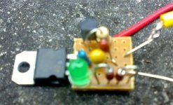
Ouuups.....I'm sory.
BTW, this morning I measured in the reg. circuit (running with 12V DC suplly) and I got:
1. Output = 4.94 V
2. Between zener - ground = 0.8 V (2 zener in seri = 1.6 V)
3. Between LED - zener (LED pin+ / LED pin-) = 2.1 V
4. Between adj.pin - ground = 3.7V
Here is the pic ( sory with a bit blur.....by phone cellular)
Attachments
YoungSC said:Thanks Ray,
Looks like FH11 & 12 are blown.
Can I use any fuse to replace them, or do I need the time delay ones?
I would defo stick FF fast blow in especially as you are testing around the circuit.
Brent
- Home
- Source & Line
- Digital Source
- Marantz CD63 & CD67 mods list