rowemeister said:
Hi aquar
There is no sch of the star ground. All I did was run ground wires from all my regulators , clocks and ic's to one point. For me this point was on a seperate pcb near the mains switch.
On other cd players I use the ground of capacitors C801/C802.
Here is a pic of my ground location. A bit blured but you get the idea.
An externally hosted image should be here but it was not working when we last tested it.
Brent
Hi Brent,
Why you didn't conexted ground of C801/802 to separate pcb (ground star) too ?
Regards
aquar
6h5c said:
Hi Aquar,
Hm, that's not right. The output voltage should be constant, independent of the input voltage. Are you sure you used the correct pinning of the regulator (ADJ - OUT - IN for LM317)? With 150 ohm there's over 8mA going through the LEDs, should be plenty to make them light. Something is probably not connected properly.
Regards,
Ray
Hi Ray,
I will check again.
One question:
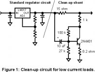
I found 'clean up shunt' from Wenzel associates, What your opinion if I combine with 5V/12V raygulator ?
Regards
aquar
Attachments
aquar said:
Hi Brent,
Why you didn't conexted ground of C801/802 to separate pcb (ground star) too ?
Regards
aquar
I did connect C801 C802 to this star. What I meant was I moved star to this location (due to amount of wires).
Brent
That circuit does work, but it needs very careful trimming to get the best noise rejection.I found 'clean up shunt' from Wenzel associates, What your opinion if I combine with 5V/12V raygulator ?
It also sounds grim! 🙁
Lowest noise out of a regulator seems to be a lot less important than its dynamic response (maintaining low impedance over the audio band). The shunt delivers low noise at the cost of rather high impedance in the supply... not good for audio, though very useful for many instrumentation uses.
Last night I had the return leg @ Simons house to check out his system.
A great night was had with good tunes and good real ales.
His system was a joy to listen too, the bass was superb with the addition of the uber sub. The sub was integrated nicely into the mix with no over blown bass. The system retrieved a really good level of detail with very smooth midrange that engaged you. The whole sound was effortless.
One quality test disc we played had some dance music that had a Robin S track, this was so clear and punchy and accurate. I await a copy of that cd 😉
The diffusors etc nailed around his room make a huge difference, they allow the music to be played loud with virtually no harsh or reflective sound, it was very good indeed....now I need to get divorced so I can have some LOL
Brent
Thanks Brent, nice to have my system/room reviewed!
One thing that does seem apparent comparing these systems is how much more detailed and clear your player is. Obviously low noise regs are needed everywhere, along with the best clocks in both locations. And topped off with Ray's discrete output stage the detail, clarity and naturalness is breathtaking.
If only you were playing it in my room!!! 😀

I've just received an Arcam 8SE dac board. Arcam have kindly provided me with the board service manual.
The dac is a Pulse width modulator SM5864AP which appears similar to the SM5872 chip in the Marantz cd63.
Arcam employ a '1-bit DAC latch' based on a 74VHC74 on the SM5864AP PWM outputs. The latch on the PWM outputs was discussed a while back on the thread as not really of much benefit. The output pwm signal in the datasheets appear the same so why did Arcam add the extra latch circuits?
adinica said:Which is the op-amp in Arcam 8SE? Maybe NJM2114D, as in the 7/7SE? Thanks!
Edit: opa2134 first stage with OP27 second stage.
Hey all,
well I managed the first 250 pages!!! Will the Pass Labs D1 I/V stage work with the CD63??
Sorry if this has been covered, like I say,its a rather looooooooooooooooooooooooooooooong thread now 😀
well I managed the first 250 pages!!! Will the Pass Labs D1 I/V stage work with the CD63??
Sorry if this has been covered, like I say,its a rather looooooooooooooooooooooooooooooong thread now 😀
stueyh said:Hey all,
well I managed the first 250 pages!!! Will the Pass Labs D1 I/V stage work with the CD63??
Sorry if this has been covered, like I say,its a rather looooooooooooooooooooooooooooooong thread now 😀
Hi - not sure I understand what you are asking. The NPC SM5872BS DAC provides differential PWM voltage outputs. There is no I/V conversion required (or possible) as it's already V.
Glenn
Again...
Any idea?
Thx
Malefoda said:
So any advices for my headphones amp? It's a now and then use, so I think there's right now no need of a real headphones amp, but I want to make a good use of the CD53's one.
Thanks.
note: the Jones' performance was very nice, and on the web you can find Krall has done the same at Studio 104 from this radio.
Any idea?
Thx
I wanted to quote a quote... it failed.
"First, I've now a gain at my Hphones opamp of... 1! So It's almot useless here, is it ok to remove all? I mean bypass all hphones pcb (and remove stuff) and wire from C901/C902 (removed) to J901. Then may C980 be upgraded for sound?"
So again the question of this opamp use...
"First, I've now a gain at my Hphones opamp of... 1! So It's almot useless here, is it ok to remove all? I mean bypass all hphones pcb (and remove stuff) and wire from C901/C902 (removed) to J901. Then may C980 be upgraded for sound?"
So again the question of this opamp use...
Hi,
If you want to use the headphone circuit you should leave the opamp in. It acts as a buffer and supplies the extra power needed to drive the phones. You can replace it by a LM4562 or other opamp. Use good caps for C901 and 902 as they provide the signal to the opamp. C903 and 904 can be upgraded to more audio-friendly types, like Pana FC, your favorite Elna's or Ruby BG. Make sure to remove the muting-transistors QN91/92.
C980 only provides a HF path for noise that enters the player through the long headphones cable, there's no sense in upgrading it. You may even be better off without it, but you have to experiment with that.
Regards,
Ray
Thanks for answering Ray,
so it's already good: muting stuff removed, 0,1% resistors with the ones left from the main upgrade, Elna RJH around the LM4562 😉
I've changed the ceramic C980 for a Wima MKS, at least made no harm to sound. Also bypassed C901/902, are those 2 last changes good?
so it's already good: muting stuff removed, 0,1% resistors with the ones left from the main upgrade, Elna RJH around the LM4562 😉
I've changed the ceramic C980 for a Wima MKS, at least made no harm to sound. Also bypassed C901/902, are those 2 last changes good?
An externally hosted image should be here but it was not working when we last tested it.
One note of caution with op-amps in headphone circuits - be careful of offsets. One to really avoid is the AD826 which sucks enormous bias currents and can generate large DC offsets which you don't want going into your 'phones. (It may be more of a problem if you've played around with the gain of the headphone circuit too as this could unbalance bias currents between inverting and non-inverting inputs.)
Any of the FET-input devices should be fine though.
Also, if you take out the muting transistors you may get rail voltages going into your phones briefly upon switching on and off.
Basically I'm just advising that you measure these DC voltages before you plug your precious headphones in, not trying to scare you!
Malefoda said:Thanks for the advice, I'll check this asap. How much DC is the limit?
This might help.
Hello All,
Looks like I've done one mod too many
I did the separate power supply mod and now when I switch on, the disc spins madly.
I had a separate supply to the clock, when it was hooked up, the on board LED didn't light up and I only measured 1.6V going into it, even though it measured 12V off the reg. When this was the case, the disc would spin faster than normal then stop and read 'disc' on the display.
I reconnected the clock supply to the original 12V and the LED came on, but I am getting the mad continuous spinning.
For the separate 5V supply that still remains, I have measured about 5V coming off each reg. If I measure the point where this power goes into the board (RD01, RD04, U199, R508,R511) against a ground on the board, every one is measuring between 1.3V and 1.6V.
I have measured pin 2 & 9 on Q104,Q105 & QM01 and they are getting about +/- 12V.
I'll go and check the continuity of the ribbons to make sure they're not the culprit.
Any suggestions would be greatly appreciated. This was the last significant mod I was planning to make and I would love to have a working player to show for my labour.
Thanks,
Simon (Oz)
- Home
- Source & Line
- Digital Source
- Marantz CD63 & CD67 mods list