Malefoda said:Also bypassed C901/902, are those 2 last changes good?
Glenn2 said:One note of caution with op-amps in headphone circuits - be careful of offsets.
You may want to keep C901/902 in the circuit considering this. They block the offset coming from the output opamp.
Ray
YoungSC said:...
I reconnected the clock supply to the original 12V and the LED came on, but I am getting the mad continuous spinning.
For the separate 5V supply that still remains, I have measured about 5V coming off each reg. If I measure the point where this power goes into the board (RD01, RD04, U199, R508,R511) against a ground on the board, every one is measuring between 1.3V and 1.6V.
Thanks,
Simon (Oz)
Simon,
Looks like you have a PSU problem. First make sure all the 5V are present. The disc spinning also occurs when the master clock is missing. Do you have a scope to check the DAC's clock signal?
Ray
Hi Ray,
Thanks for the reply.
I don't have an oscilloscope, but maybe someone I know owns one.
I was thinking about putting all the resistors back in and removing the new power supply to see what happens.
Simon (Oz)
Thanks for the reply.
I don't have an oscilloscope, but maybe someone I know owns one.
I was thinking about putting all the resistors back in and removing the new power supply to see what happens.
Simon (Oz)
That's a start, just reverse the last mods step-by-step and see what happens. But on the other hand it shouldn't matter whether the circuit gets its supply from the board or externally, as long as the right voltages are present. If there's 5V off each reg but only 1.6V at the board, maybe there's a wiring problem. Are the grounds of the board and the external PSU properly connected?
Ray
Ray
6h5c said:That's a start, just reverse the last mods step-by-step and see what happens. But on the other hand it shouldn't matter whether the circuit gets its supply from the board or externally, as long as the right voltages are present. If there's 5V off each reg but only 1.6V at the board, maybe there's a wiring problem. Are the grounds of the board and the external PSU properly connected?
Ray
Hi Ray and Simon (oz)
Regarding with my experience, wiring problem in the regs (5V) can get 5V but if connected with other DC source will get different result so I have a tips to final check with a few of DC source, the right wiring will be get the same result, always.
Lately I got 4.94 V (2 zener seri with green led in the adj pin), can I use for 5V supply ?
Regards
aquar
martin clark said:That circuit does work, but it needs very careful trimming to get the best noise rejection.
It also sounds grim! 🙁
Lowest noise out of a regulator seems to be a lot less important than its dynamic response (maintaining low impedance over the audio band). The shunt delivers low noise at the cost of rather high impedance in the supply... not good for audio, though very useful for many instrumentation uses.
Hi martin,
Tks for your kind answering, I'll keep in my mind.
Regards
aquar
Aquar, it is possible the voltage collapses as soon as it is loaded with current. A measurement with a (high-impedance) DVM will show a neat 5V, but as soon as you hook it up to anything the voltage drops. If the common ground is poorly connected or the regulator is wired incorrectly this can occur.
So you managed to get the circuit to work? 4.94V is perfect for 5V, you can't get any closer I guess 🙂
Which zener values did you use?
Ray
So you managed to get the circuit to work? 4.94V is perfect for 5V, you can't get any closer I guess 🙂
Which zener values did you use?
Ray
6h5c said:
You may want to keep C901/902 in the circuit considering this. They block the offset coming from the output opamp.
Ray
Glenn2 said:
I've checked. -28mV/-32mV. They advise 20 is OK... maybe I'll have a try with C901/902 back, but won't they disturb the main RCA outlet?
Malefoda said:I've checked. -28mV/-32mV. They advise 20 is OK... maybe I'll have a try with C901/902 back, but won't they disturb the main RCA outlet?
No - if anything they will isolate the two parts of the circuit from each other.... it certainly won't cause a negative effect on the RCA. This offset may be (probably) coming from the filter op-amps - does it measure roughly the same there? Is it a similar offset on your RCA outs?
If it does, these caps would block it. If it doesn't, re-instating them would not get rid off your offset and it's coming from the headphone circuit itself anyway.
If you decide you need them you could replace them with decent film caps... a couple of uF is all you need.
I doubt that 30mV is going to fry your cans but getting rid of it might help you sleep at night.
Glenn
Glenn2 said:I doubt that 30mV is going to fry your cans but getting rid of it might help you sleep at night.
Glenn you know me!
I won't sleep until this is defintly over and under control 🙂 Even if for a very stupid volume control hphones...
No - if anything they will isolate the two parts of the circuit from each other.... it certainly won't cause a negative effect on the RCA. This offset may be (probably) coming from the filter op-amps - does it measure roughly the same there? Is it a similar offset on your RCA outs?
If it does, these caps would block it. If it doesn't, re-instating them would not get rid off your offset and it's coming from the headphone circuit itself anyway.
If you decide you need them you could replace them with decent film caps... a couple of uF is all you need.
The RCA show 30/25mV and hphones 27/32mV. Very close! I think I'll have a try with caps back, I've in hand 1uF Wima MKS. I use to see electrolytic caps on audio path, no? Will they do fine? OEM is 47/25.
Thanks Glenn
YoungSC said:Hi Ray,
Thanks for the reply.
I don't have an oscilloscope, but maybe someone I know owns one.
I was thinking about putting all the resistors back in and removing the new power supply to see what happens.
Simon (Oz)
Sounds like the ground of the new psu is not connected to the ground of the main pcb.The ground is the reference and if one is floating the output voltage will be wrong.
Wire the ground from psu to C801 C802 ground
Brent
Errr.....ummmm......(cough)...........yes............well.........I haven't grounded the power supply
What was that?
I....umm..... haven't grounded the power supply
You what!!!! You fool!!!! Why not?!?
I thought that the wire going back to the tranformer was the earth
Well I'm surprised that you haven't electrocuted yourself you gormless twit!!
I'll get right on it
What was that?
I....umm..... haven't grounded the power supply
You what!!!! You fool!!!! Why not?!?
I thought that the wire going back to the tranformer was the earth
Well I'm surprised that you haven't electrocuted yourself you gormless twit!!
I'll get right on it
lol, I had the same problem when I did my first external power supply! The grounds must all be connected or it won't be happy!
I do hope it works for you now.
Simon (UK)
I do hope it works for you now.
Simon (UK)
OFF TOPIC - schroeder diffuser
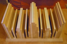
Sorry this is off-topic, but if anyone is interested in what was for me a very very important upgrade, have a look at this. It's a diffuser built on the maths of quadratic residues. I can whole-heartedly recommend F. Alton Everest's "Master Handbook of Acoustics" for anyone wishing to make their room sound less rubbish.
Sorry this is off-topic, but if anyone is interested in what was for me a very very important upgrade, have a look at this. It's a diffuser built on the maths of quadratic residues. I can whole-heartedly recommend F. Alton Everest's "Master Handbook of Acoustics" for anyone wishing to make their room sound less rubbish.
Attachments
Still off-topic
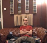
Here's the diffuser in situ, "modelled" by my friend "Hairy John", who said "that picture better not go on the Internet!"
In this position the too-close rear wall is made less evil by having lateral reflections diffused so as to minimise conflicting left-right information. The sound is great: images have more of a solid position now and I can play loud with great clarity!
Potentially a useful mod for anyone who has trouble hearing their CD player upgrades.
Simon
Attachments
YoungSC said:P.S.
Thankyou Brent and Ray for your sage advice.
Simon (Oz)
😀
You're welcome! Glad things are solved now with your player 😀.
Ray
Re: OFF TOPIC - schroeder diffuser
Hey, that looks vey nice Simon. I happen to have some reflections on the left side, but I doubt I will ever get such thing into my livingroom, low WAF, you know... Maybe if John comes with it, depends on where the hairy part is...😀
Ray
SimontY said:Sorry this is off-topic, but if anyone is interested in what was for me a very very important upgrade, have a look at this. It's a diffuser built on the maths of quadratic residues. I can whole-heartedly recommend F. Alton Everest's "Master Handbook of Acoustics" for anyone wishing to make their room sound less rubbish.
Hey, that looks vey nice Simon. I happen to have some reflections on the left side, but I doubt I will ever get such thing into my livingroom, low WAF, you know... Maybe if John comes with it, depends on where the hairy part is...😀
Ray
- Home
- Source & Line
- Digital Source
- Marantz CD63 & CD67 mods list