rowemeister said:sweet. I like the idea of removing the outer sleeve.
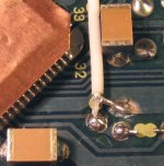
I only did the 16.9MHz MCLK that runs from the DAC to the decoder for starters. It's a job that requires a good light, and a sharp scalpel knife 😎. I bought the cable at Farnell, it's from Nexans. Overall diameter is 1.22mm! The inner conductor is a 0.1mm copper plated steel wire. Very cool stuff! Felt like a surgeon this afternoon 😀.
Originally posted by ash_dac
75 ohm or 50 ohm ?
I used 75 ohm because that has less capacity/m.
The characteristic impedance doesn't matter much, because it's such a short run, compared to the signal's wavelength. I learned that here. Very good site, with lots of info. So I went for less capacity.
Standard there's a 470R resistor in series with the MCLK line. I noticed the clock signal became quite weak at the decoder after I inserted the coax, probably because of the larger capacity. I tried lowering the resistor to 75R. But the input of the decoder appears to be at ~2.5V DC, and there is actually a DC current running between the two chips
 . That's probably why they chose the resistor so high. So I also inserted a 560pF SMD cap (had that laying around...) in series with the DAC's output, after the 75R resistor, and got rid of that. The signal is a lot stronger now and the decoder seems to work fine.
My first impression of the sound is that it has become more like my tubestage 😀 😀.
This is definately a mod I can recommend. Thank you Brent!
Regards,
Ray.
I'm just wondering if anyone has gotten around to biasing the the outputs into class A and if it made a difference.
6h5c said:
I only did the 16.9MHz MCLK that runs from the DAC to the decoder for starters. It's a job that requires a good light, and a sharp scalpel knife 😎. I bought the cable at Farnell, it's from Nexans. Overall diameter is 1.22mm! The inner conductor is a 0.1mm copper plated steel wire. Very cool stuff! Felt like a surgeon this afternoon 😀.
I used 75 ohm because that has less capacity/m.
The characteristic impedance doesn't matter much, because it's such a short run, compared to the signal's wavelength. I learned that here. Very good site, with lots of info. So I went for less capacity.
Standard there's a 470R resistor in series with the MCLK line. I noticed the clock signal became quite weak at the decoder after I inserted the coax, probably because of the larger capacity. I tried lowering the resistor to 75R. But the input of the decoder appears to be at ~2.5V DC, and there is actually a DC current running between the two chips
My first impression of the sound is that it has become more like my tubestage 😀 😀.
This is definately a mod I can recommend. Thank you Brent!
Regards,
Ray.
Just wait till you do the other coax mate, very worth while 😉
Also my 63 has a cap and resistor between Dac and Decoder. The resistor is a 390ohm and the cap (I can't remember value) which I changed for a silver mica

Strange thing is the service manual shows no cap and a 100 ohm res!!!
Brent
How NOT to do a Mod !!
Hi.
I thought you might be interested in my latest project.
I have been asked to look at a CD6000 OSE. The guy had attempted to upgrade it by changing the rectifiers to Schkktsky ( you know what I mean - better ones ). When he switched on, it didn't work. He found he hed soldered 1 diode the wrong way round ( in the 10 / 5v supply ). So he corrected the fault and it still didn't work.
This model does not use glass fuses as per CD63 but PCB mount Wickmann fuses - both were blown, naturally!
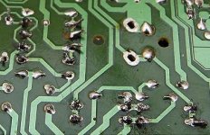
But look at the soldering - I think he used a piece of steel rod and a lump of old lead pipe to solder the joints - every one is dry.
The sad thing is that this attempt to mod his CD-P disheartened him so much that he purchased a ready-modded one off Ebay. It was dead on arrival!!
Andy
Hi.
I thought you might be interested in my latest project.
I have been asked to look at a CD6000 OSE. The guy had attempted to upgrade it by changing the rectifiers to Schkktsky ( you know what I mean - better ones ). When he switched on, it didn't work. He found he hed soldered 1 diode the wrong way round ( in the 10 / 5v supply ). So he corrected the fault and it still didn't work.
This model does not use glass fuses as per CD63 but PCB mount Wickmann fuses - both were blown, naturally!
But look at the soldering - I think he used a piece of steel rod and a lump of old lead pipe to solder the joints - every one is dry.
The sad thing is that this attempt to mod his CD-P disheartened him so much that he purchased a ready-modded one off Ebay. It was dead on arrival!!
Andy
Attachments
Standard there's a 470R resistor in series with the MCLK line. I noticed the clock signal became quite weak at the decoder after I inserted the coax, probably because of the larger capacity. I tried lowering the resistor to 75R. But the input of the decoder appears to be at ~2.5V DC, and there is actually a DC current running between the two chips . That's probably why they chose the resistor so high. So I also inserted a 560pF SMD cap (had that laying around...) in series with the DAC's output, after the 75R resistor, and got rid of that. The signal is a lot stronger now and the decoder seems to work fine.
Hi Ray,
isnt MCLK from decoder to DAC? So you added a 560pF cap in series with the dacs input? Sorry not trying to be padantic, but I want to try this one and want to understand what to do.
Also in the schematic there is a 10pF cap to ground before the 470ohm resistor. Did you leave this in place?
Can inagine that if there is 2.5V DC getting to DAC input as well as signal, then this must be harmful to sound quality.
Nice work!
Seeya arthur
Re: How NOT to do a Mod !!
Oh dear!!!
Looks like its been soldered by a flock of seagulls
I too have a 63 KI here that has soldering like that (bought off ebay) and the TX is O/C has it was fitted the wrong way round shorting a v rail to gnd.!!!
Thats why I want one of these custom TX
poynton said:Hi.
I thought you might be interested in my latest project.
I have been asked to look at a CD6000 OSE. The guy had attempted to upgrade it by changing the rectifiers to Schkktsky ( you know what I mean - better ones ). When he switched on, it didn't work. He found he hed soldered 1 diode the wrong way round ( in the 10 / 5v supply ). So he corrected the fault and it still didn't work.
This model does not use glass fuses as per CD63 but PCB mount Wickmann fuses - both were blown, naturally!
But look at the soldering - I think he used a piece of steel rod and a lump of old lead pipe to solder the joints - every one is dry.
The sad thing is that this attempt to mod his CD-P disheartened him so much that he purchased a ready-modded one off Ebay. It was dead on arrival!!
Andy
Oh dear!!!
Looks like its been soldered by a flock of seagulls
I too have a 63 KI here that has soldering like that (bought off ebay) and the TX is O/C has it was fitted the wrong way round shorting a v rail to gnd.!!!
Thats why I want one of these custom TX
Hi Brent,
whats a used CD63KI sell for on ebay? We dont really have it in NZ, we use trademe.co.nz but Ive never seen one of these selling.
seeya Arthur
whats a used CD63KI sell for on ebay? We dont really have it in NZ, we use trademe.co.nz but Ive never seen one of these selling.
seeya Arthur
Re: CD6000 PSU
Very similar to the CD17. I like the 12v reg used though.
poynton said:Hi
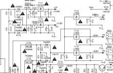
Take a look at the CD6000 psu.
Marantz must have realised that the psu as used in the CD63 was inadequate.
They still take all the +5v feeds from the same Tx but at least they are indevidually regulated.
Andy
Very similar to the CD17. I like the 12v reg used though.
Attachments

Luke said:Hi Brent,
whats a used CD63KI sell for on ebay? We dont really have it in NZ, we use trademe.co.nz but Ive never seen one of these selling.
seeya Arthur
Usually go for £150 - £200. Sometimes you can get a bargain.
I get them faulty for roughly £50 and repair.
Re: Re: CD6000 PSU
Noisy zener and Darlington ..... ?
No need for better? supply because of CM rejection? Must have had problems hence the fuse?
Each 5v has its own bridge - any ideas why?
Andy
rowemeister said:
Very similar to the CD17. I like the 12v reg used though.
Noisy zener and Darlington ..... ?
No need for better? supply because of CM rejection? Must have had problems hence the fuse?
Each 5v has its own bridge - any ideas why?
Andy
Re: Re: Re: CD6000 PSU
To isolate the DC. I have implimented this on two of my regs. Share the ac but keep the dc seperate.
poynton said:
Noisy zener and Darlington ..... ?
No need for better? supply because of CM rejection? Must have had problems hence the fuse?
Each 5v has its own bridge - any ideas why?
Andy
To isolate the DC. I have implimented this on two of my regs. Share the ac but keep the dc seperate.
DJNUBZ said:I'm just wondering if anyone has gotten around to biasing the the outputs into class A and if it made a difference.
Hi DJNUBZ,
No, I haven't tried it yet. A friend of mine has, and he reported a positive change. But as soon as my tubestage is done I want to do a comparison between the players I have, and in one of them I want to bias the opamps in class-A. But if you want to try it yourself, it's a 5 minute mod. Just solder a resistor between each output and the negative voltage rail. Somewhere between 3k3 and 3k9 for +/-12V supply. That should give you a pretty good idea of the change in sound. If you like it you can change the resistor into a more sophisticated FET current sink.
Probably posted this already: http://tangentsoft.net/audio/opamp-bias.html
Regards,
Ray.
Re: How NOT to do a Mod !!
Then you must have a MKII too, the cap is 10pF here. Why so small I wonder? The manual is an earlier version, probably standard CD63.
Sad story.....
So now he has two broken players?
Regards,
Ray.
rowemeister said:Also my 63 has a cap and resistor between Dac and Decoder. The resistor is a 390ohm and the cap (I can't remember value) which I changed for a silver mica
Strange thing is the service manual shows no cap and a 100 ohm res!!!
Brent
Then you must have a MKII too, the cap is 10pF here. Why so small I wonder? The manual is an earlier version, probably standard CD63.
poynton said:The sad thing is that this attempt to mod his CD-P disheartened him so much that he purchased a ready-modded one off Ebay. It was dead on arrival!!
Andy
Sad story.....
So now he has two broken players?
Regards,
Ray.
Ray mine is a MKII and the sevice manual I have had since the day of release - 'First Issue : 1993/8'
So there are a few differences.
So there are a few differences.
Luke said:Hi Ray,
isnt MCLK from decoder to DAC? So you added a 560pF cap in series with the dacs input? Sorry not trying to be padantic, but I want to try this one and want to understand what to do. Also in the schematic there is a 10pF cap to ground before the 470ohm resistor. Did you leave this in place?
Can inagine that if there is 2.5V DC getting to DAC input as well as signal, then this must be harmful to sound quality. Nice work!
Seeya arthur
Hi Arthur,
Thanks! I'm very pleased with the result, and I want to do the other signals too.
In this case the master clock signal is generated by the DAC (or an external clock if you installed one) and then buffered by an internal gate. From there (pin4/CKO/clock out) it runs to the decoder through RD14. The decoder, in return, delivers SCLK (BCKI), WCLK (LRCI) and DATA (DI) signals to the DAC.
The 10pF cap (CD01) was not present in my player, so I didn't have to remove it 😀
I didn't like the idea of DC either, so I inserted the 560pF cap. My guts say it should be a bit bigger, but I didn't have any in SMD.
Regards,
Ray.
Ray
what's the clock signal like before and after the 560pF cap on the scope.
the cap should stop the dc and the cap size depends only on frequency ie doesn't distort the clock.
please correct me if i'm wrong
allan
ps could to see the patient's still alive😀
??dc out of dac??
what's the clock signal like before and after the 560pF cap on the scope.
the cap should stop the dc and the cap size depends only on frequency ie doesn't distort the clock.
please correct me if i'm wrong
allan
ps could to see the patient's still alive😀
??dc out of dac??
- Home
- Source & Line
- Digital Source
- Marantz CD63 & CD67 mods list