Hi Brentrowemeister said:
Cut the track near U100 fo the signal no longer goes down the ribbon.
If I lift U100 and solder there the coax, I will not need to cut the track right ?
rowemeister said:
Solder the coax onto U100 and use U101 for the gnd. Also link this gnd to star. Connect Coax up to R501 and no gnd at that end.
If I connect U101 to the star GND, I might be creating a gnd loop because U101 links to the main pcb gnd using the mesch.
How can I avoid the loop ?
Regards
Ricardo
RCruz said:If I lift U100 and solder there the coax, I will not need to cut the track right ?
It was a long time ago but I'm pretty certain that's how I did it (and I don't think it blew up!)
You'll be fine, and you will enjoy the cleaned up top end. With your clocks and regs already done it will have wonderfully crisp and detailed treble.
Simon
cd67 coax mod
Hi all,
After reading the recent posts about coax mod am i right that on a 67 the relevant bits are cut u101 use u100 for ground then connect at r105 on main pcb ? It seems the 67 schematic is different in this area also.
Many thanks to the brains
ian
Hi all,
After reading the recent posts about coax mod am i right that on a 67 the relevant bits are cut u101 use u100 for ground then connect at r105 on main pcb ? It seems the 67 schematic is different in this area also.
Many thanks to the brains
ian

RCruz said:
Hi Brent
If I lift U100 and solder there the coax, I will not need to cut the track right ?
If I connect U101 to the star GND, I might be creating a gnd loop because U101 links to the main pcb gnd using the mesch.
How can I avoid the loop ?
Regards
Ricardo
Yes you can lift the link if you like. Also if you already have the pcb gnd connected to the star don't add the other one.
Brent
Re: cd67 coax mod
Looking at the CD67 sch and general layout of the 67 in this area and i'm not sure the gains would be much as the signal distance is very small compared to the 63.
If you do use coax (which is better than the ribbon) then you need to connect from the RF pin on either the IC (Q101) or the connector and then connect the other end to R501 which is the other side of the connector. Don't forget to lift R501
Brent
ian21 said:Hi all,
After reading the recent posts about coax mod am i right that on a 67 the relevant bits are cut u101 use u100 for ground then connect at r105 on main pcb ? It seems the 67 schematic is different in this area also.
Many thanks to the brains
ian
Looking at the CD67 sch and general layout of the 67 in this area and i'm not sure the gains would be much as the signal distance is very small compared to the 63.
If you do use coax (which is better than the ribbon) then you need to connect from the RF pin on either the IC (Q101) or the connector and then connect the other end to R501 which is the other side of the connector. Don't forget to lift R501
Brent
Hi all
Ive been following this thread for a while now and started to mod my Marantz CD63. but im unsure on a few things
when replacing the Standard power Regs 7805, 79M12 and 78M12.
do 79M12 and 78M12 feed the Opamps? also feed other things?
how do you give the opamps there own super reg power
I would like to be able to power everything separately but unsure on how to do it or if it has much gain
I know the voltages but what Current/Amps do the Power Reg need to be able to handle?
how do you power an a clock from an external power source. does this mean taping of the current +10 and using a SuperReg for the clock?
also is it work replacing 79M18
Thanks
🙂
Hi e1roy
The +/- 12V regs are indeed for powering the opamps + hdam. Just replacing these regs with good quality ones will bring good gain (along with better caps). But moving these regs right next to the opamps brings further gains. Any TO220 reg would be fine current wise but the better regs can supply any voltage/current demand quicker than the cheap oem types as well as being lower noise.
The best way to supply a clock is to have a dedicated psu for it, this isolates it from the main circuit much better.
The 7918 is just for the display, changing this for a 7912 would dim the display more then shorting out D852 dims the display further. Doing this almost shuts the display off at the lowest dimmer setting.
Brent
Thanks for the picture Lee and the consise reply Brent, these have made it lots clearer... something else for the Christmas break... going to make a few Ray regs as well.
Cheers guys
Ian
Cheers guys
Ian
Oh things goin' on here, nice!
Simon don't stop making bubbles, each popped gives 10 points!
Simon don't stop making bubbles, each popped gives 10 points!
Malefoda said:Oh things goin' on here, nice!
Simon don't stop making bubbles, each popped gives 10 points!
I think Simon is up to 140 now 😀 and could be more if we added a bonus system 😉
Brent
Thanks Brent
I have already disable the HDAM, remove muting trans.
so to move the 7812/7912 +/-12 regs closer to the Opamps,
look at the service manual I see that
Q606 gets -12 from R616 +12 from R614
and Q605 -12 from R615 +12 from R613
is that correct?
connecting the Sregs fro OPamps
I know where to connect the Input but Im not sure on the Output and common for the SRegs to Power the Opamps, do you need 4 sRegs, each opamp has its own +/-12 SReg?
where else can I install Sregs? is there a list on which pins you connect to and from
Thanks
Elroy
rowemeister said:Hi e1roy
The +/- 12V regs are indeed for powering the opamps + hdam. Just replacing these regs with good quality ones will bring good gain (along with better caps). But moving these regs right next to the opamps brings further gains. Any TO220 reg would be fine current wise but the better regs can supply any voltage/current demand quicker than the cheap oem types as well as being lower noise.
The best way to supply a clock is to have a dedicated psu for it, this isolates it from the main circuit much better.
The 7918 is just for the display, changing this for a 7912 would dim the display more then shorting out D852 dims the display further. Doing this almost shuts the display off at the lowest dimmer setting.
Brent
Hi Elroye1roy said:
I know where to connect the Input but Im not sure on the Output and common for the SRegs to Power the Opamps, do you need 4 sRegs, each opamp has its own +/-12 SReg?
where else can I install Sregs? is there a list on which pins you connect to and from
Just move two regs near the opamps... I placed them instead of the psu resistors feeding the opamps.
Other very eficient place for sreg is DAC analog ... but there you really need a SREG like a spower.
Ricardo
RCruz said:
Quote "Also think about bypassing the ribbon from mech to main pcb as this causes no end of problems."
thanks .... i try to check it again really sad 🙁
RCruz said:Please verify if the chip is a TCA0372DP2.... I have some spare and can send you one if you wish.
Regards
Ricardo
i see got 2 TCA0372DP2 Q105 & Q106 which one u refer 🙂
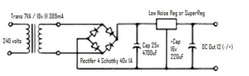
Yes that psu will work fine. Do not use a cap after the reg if the clock has a cap on its voltage input. The Pana FC 25V 4700uF is a good starting block for this application, if you can go bigger to a Mundorf HC or BHC aerovox then do so (only if you use a quality reg though to reap the benefits).
Brent
Brent
Also when moving the Regs closer to the Opamps.
do I connect it as follows?
-input voltage from +POS side of C803
Gnd to Gnd plane
Output into R613 to feed +12 into Q605/Q606 Opamps
disconnect U210?
-input voltage from -NEG side of C804
Gnd to Gnd plane
Output into R616 to feed -12 into Q605/Q606 Opamps
disconnect U216?
so 7912 and 7812 also feed decoder? or DAC also?
Thanks for your help
e1roy said:Also when moving the Regs closer to the Opamps.
do I connect it as follows?
-input voltage from +POS side of C803
Gnd to Gnd plane
Output into R613 to feed +12 into Q605/Q606 Opamps
disconnect U210?
-input voltage from -NEG side of C804
Gnd to Gnd plane
Output into R616 to feed -12 into Q605/Q606 Opamps
disconnect U216?
so 7912 and 7812 also feed decoder? or DAC also?
Thanks for your help
Yes to the wiring of the 12v regs (expept I think U210 was a typo 😉 ).
Everything else on the pcb runs off the one 5v reg!!!!!!
Brent
OT but picked up a Squeezebox Classic (aka SB3) yesterday.
I know they can be improved by getting rid of the SMPS, and only apparently come into their own when feeding a DAC...
...but out of the box (and after 24hrs run in) it sounds like.... well... $hit really.
Perhaps it's a little unfair to A/B it with a souped up 63. 😀
Still, plenty of options to improve it. Maybe a Cambridge dac.
- Home
- Source & Line
- Digital Source
- Marantz CD63 & CD67 mods list