I noticed that Ray's filter circuit has a much lower input impedance than the stock player. Around 1/10th. This is similar to the ultranalog SACD enhancer it is based on, but that is for an AKM DAC.
I'm wondering if this has any efffect - good or bad - on audio performance.
Also, can anyone tell me what we are filtering out here. Obviously we want to pass up to 20kHz, but where does the rubbish start? Is it all above 300kHz?
I'm wondering if this has any efffect - good or bad - on audio performance.
Also, can anyone tell me what we are filtering out here. Obviously we want to pass up to 20kHz, but where does the rubbish start? Is it all above 300kHz?
Glenn2 said:I noticed that Ray's filter circuit has a much lower input impedance than the stock player. Around 1/10th. This is similar to the ultranalog SACD enhancer it is based on, but that is for an AKM DAC.
I'm wondering if this has any efffect - good or bad - on audio performance.
Well it sounds nice 😀
I will order the transistors this afternoon.... Hopefully can get it built soon and so have some more insightful comments to make!!
Simon
I don't doubt it Simon! Just wondered if making the DAC analogue stage work harder was detrimental at all.
Thanks Martin - I don't recall seeing that before. Quite a lot going on at 4fs too.
Thanks Martin - I don't recall seeing that before. Quite a lot going on at 4fs too.
Glenn2 said:I don't doubt it Simon! Just wondered if making the DAC analogue stage work harder was detrimental at all.
Ah, I kinda read your post as "output impedance" which I assumed would be good. Now I see you wrote input impedance. Yeh I wonder. Could we change it easily?
Simon
Not without a bigger value inductor I think.
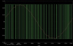
I played around with it a bit in a simulator but without changing L, only R and C. It rolls off a bit too late really. Flat-ish (or even a little peaky) out to 100kHz. Not bad though. I think it was about 55dB down at 8fs (352.8kHz).
I played around with it a bit in a simulator but without changing L, only R and C. It rolls off a bit too late really. Flat-ish (or even a little peaky) out to 100kHz. Not bad though. I think it was about 55dB down at 8fs (352.8kHz).
opamp
Hi there!
back with some stupid questions, first some more opinions about caps
http://www.diyaudio.com/forums/showthread.php?postid=1206241#post1206241
even if I read some said the Philips MKC sounds very good so it seems my integrated amp is perfect ! It's a jungle to find what is the best for what... I'll get capsed soon!
About the opamps, is there something that came makes the AD8599 sounds not "happy" but "beyond excited"? The caps? I've beside them the old Ray's list stuff, Elna RJH. Maybe time for BG.
I've tried the impact of the AD8599 on the HPhones socket: OMG! No way to use it anymore! The low mids and mids seam lost. Highs are over present. I'm scared I'll loose the bass and the beatif fit back the LM4562. Very hard to say! The bypass cap? Again, some said a cap between 4&8 is stupid, 4&GRND and same for 8 is the way. My 4&8 cap is a 0.22µf Wima MKS4.
I really want to change the opamp asap, but it is wise to put tulip socket there.
I really something is wrong on my setup makes the AD sounds like this.
AVR, what is your caps setup around there?
Again, what is the real size forthe socket? Farnell shows thousand!
http://fr.farnell.com/jsp/Supports+...ARWIN/D2608-42/displayProduct.jsp?sku=1023046
Is this one ok?
Thanks 😉
Note: I know that a guy talking opamps when the mood is at discret... sorry, lazyness...
Re: opamp
I was under the impression that between 4 & 8 is best, as it reduces possibility of ps noise coming "back" into the circuit.
I use these all the time and have had no problems:
http://rswww.com/cgi-bin/bv/rswww/s...feceeldgkidhgi.0&cacheID=uknetscape&Nr=avl:uk
Regards, Lee.
Malefoda said:Hi there!
Again, some said a cap between 4&8 is stupid, 4&GRND and same for 8 is the way. My 4&8 cap is a 0.22µf Wima MKS4.
I was under the impression that between 4 & 8 is best, as it reduces possibility of ps noise coming "back" into the circuit.
I use these all the time and have had no problems:
http://rswww.com/cgi-bin/bv/rswww/s...feceeldgkidhgi.0&cacheID=uknetscape&Nr=avl:uk
Regards, Lee.
Glenn2 said:Just wondered if making the DAC analogue stage work harder was detrimental at all.
Hi Glenn,
It's not an analogue stage! The output signals are square waves.
Look at the block diagram, there's a PWM modulator buffered by two drivers. The output stage is probably something like a totem-pole: on or off, with saturated transistors. So I don't think the output voltage will drop much by the increased load at the output. Well, unless you make it too low of course 😀. It's the timing of the pulses that's important, that makes the audio-signal, not the actual amplitude.
In the datasheet the output voltage is spec'd AVdd-0.3V at 1mA output current and that would be about 5k impedance.
Regards,
Ray
Attachments
Glenn2 said:
Also, can anyone tell me what we are filtering out here. Obviously we want to pass up to 20kHz, but where does the rubbish start? Is it all above 300kHz?
Without going into sampling theory, the filter roll-off is at just above 20KHz deliberately. This is approximately half the sample rate of 44KHz. The noise starts here, mainly in the form of alias signals which go all the way up to many KHz (in theory to infinity)
Similar filters are used in the recording process.
Andy
For more info, Google 'Nyquist Theory'.
poynton said:
Without going into sampling theory, the filter roll-off is at just above 20KHz deliberately. This is approximately half the sample rate of 44KHz. The noise starts here, mainly in the form of alias signals which go all the way up to many KHz (in theory to infinity)
Similar filters are used in the recording process.
Andy
For more info, Google 'Nyquist Theory'.
Hi Andy,
I just wasn't sure what the situation was with a PWM output.
Wasn't the original point of oversampling that it took the grunge up to a much higher frequency so that gentler filtering could be used? Though this was with R2R dacs.
Glenn
6h5c said:
Hi Glenn,
It's not an analogue stage! The output signals are square waves.
Look at the block diagram, there's a PWM modulator buffered by two drivers. The output stage is probably something like a totem-pole: on or off, with saturated transistors. So I don't think the output voltage will drop much by the increased load at the output. Well, unless you make it too low of course 😀. It's the timing of the pulses that's important, that makes the audio-signal, not the actual amplitude.
In the datasheet the output voltage is spec'd AVdd-0.3V at 1mA output current and that would be about 5k impedance.
Regards,
Ray
Thanks Ray. The output stage of the DAC seems to be sensitive to regulation and decoupling changes so it would not have shocked me if it was sensitive to loading too.
If it works as you describe, it makes sense that they design it to have differential outputs for noise rejection.
By the way, do you fine-tune your circuit to maximise common-mode rejection? Or just match everything to such a degree that it is not necessary?
Cheers,
Glenn

Glenn2 said:Thanks Ray. The output stage of the DAC seems to be sensitive to regulation and decoupling changes so it would not have shocked me if it was sensitive to loading too.
If it works as you describe, it makes sense that they design it to have differential outputs for noise rejection.
By the way, do you fine-tune your circuit to maximise common-mode rejection? Or just match everything to such a degree that it is not necessary?
Cheers,
Glenn
I didn't want to use any trimmers in the circuit, so I matched the components where it was nescessary. The Holco resistors I used are very close in tolerance already, so it wasn't needed for those. But I matched the filter's inductors and caps and everything in the differential input stage.
Regards,
Ray
Re: opamp
Pana FC if I remember.
No, it don't fit. Much better to find SIL version. Then you can break off any number you want.
http://fr.farnell.com/jsp/Supports+...IN/D01-9952042/displayProduct.jsp?sku=1023031
That's the way I do it.
Malefoda said:AVR, what is your caps setup around there?
Again, what is the real size forthe socket? Farnell shows thousand!
http://fr.farnell.com/jsp/Supports+...ARWIN/D2608-42/displayProduct.jsp?sku=1023046
Is this one ok?
Pana FC if I remember.
No, it don't fit. Much better to find SIL version. Then you can break off any number you want.
http://fr.farnell.com/jsp/Supports+...IN/D01-9952042/displayProduct.jsp?sku=1023031
That's the way I do it.
Attachments
Good idea and thanks for the link.
I've fitted back the LM... in fact it's all in my head, and I do need sockets to compare in blind test. Still find AD fast.
Thx
I've fitted back the LM... in fact it's all in my head, and I do need sockets to compare in blind test. Still find AD fast.
Thx
raygulator
Hi guys, i am trying to build Raygulator as i am a beginer- my question is for the 12V+ using the LM317-do i need to bend the pin at all?as i see the pins are not matched as 78M12? or am i missing something. I have looked at the pictures from Ray web site but still unsure esp even when the LM317 reverse in position . Thanks Quan.
Hi guys, i am trying to build Raygulator as i am a beginer- my question is for the 12V+ using the LM317-do i need to bend the pin at all?as i see the pins are not matched as 78M12? or am i missing something. I have looked at the pictures from Ray web site but still unsure esp even when the LM317 reverse in position . Thanks Quan.
http://www.diyaudio.com/forums/showthread.php?postid=1206171#post1206171
Ummmm... small cry for help ... 😕
k.
jksmurf said:
Is the Upper one for LM317/LM337 regs and kower 79M12? Is that the reason for the difference for pinout of +12V/-12V regs?
k.
Ummmm... small cry for help ... 😕
k.
jksmurf said:http://www.diyaudio.com/forums/showthread.php?postid=1206171#post1206171
Ummmm... small cry for help ... 😕
k.
Hi k,
I hope this pic will help you.
BTW for pic: view from top site pcb, and will be opposite if you look from soldering area.
Regards
aquar
Attachments
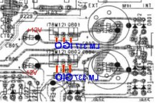
aquar said:
Hi k,
I hope this pic will help you.
BTW for pic: view from top site pcb, and will be opposite if you look from soldering area.
Regards
aquar
Thanks aquar, I'll pass it to my wife and see if she gets all that 🙂
k.
- Home
- Source & Line
- Digital Source
- Marantz CD63 & CD67 mods list