gy21 said:Ok Thanks Simonty,
What value caps did you use?
No problem 😎
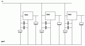
I used 33uF before and after each regulator, which isn't necessarily optimal, it's just what I felt like using.
Additionally there's a 2200uF before all of those, which is there for smoothing for when I feed it voltage from outside the box (future upgrade - toroid, schottky diodes, wire to cdp, wire to reg board).
Si
DAC output filter and supplies
Hi all,
I simulated the DAC output filter using PSpice with 1000p in C605 (original) and 470p (modified). I could see the reduction in group delay amounting to less then 3us, and when I compare it with some articles on the internet about the audiability of group delay at different frequencies being in the range of few miliseconds, I really find the improvement miniscule. It is still the loudspeaker that makes the bulk of the whole group delay and can make it exceed the ms range. On the other hand, about 1dB of gain is lost at 20kHz, maybe this is something we should worry about now???
A question about the same output filter: In the original Double-pole Multiple-feedback active filter topology, there is no inductance, like L601. What it does is, it adds a zero at around 400 kHz and obviously the attenuation of the DAC noise at higher frequencies is much lower than without it. This frequency corresponds well with the DAC sampling frequency, being 44.1 kHz X 8 times oversampling = 352.8 kHz. Do you have any clue why the designers have done it?
There have been much discussions about 5V regulators around the DAC, and I would like to share some of the things I have done. I use a single regulator for the digital section and two 5V regs for each of the analog channels. As you can see on the CD63 schematic, by removing some connections you can supply separate power to each of the audio channels and the ground connections of the right and left analog sections originally go to the star point separatelly - probably to avoid any possible crosstalk. I don't remember now quite well, but there was a chance that by installing a single reg for two channels, when connecting the ground to both of them, a ground loop is created extending to the star point. Therefore I removed the ground connections to the star point by removing some of the jumpers, and replaced them with the ground connections from the reg, taken from the 10V supply taken in a single point. Has anybody else done the same "mass"?
Cheers,
Petar
Very interesting Petar. I didn't touch the ground there and I used a single 7805 to feed all 4 analogue pins. Maybe this is something I should improve... 
Si

Si
Re: DAC output filter and supplies
Hi Petar,
You may find this and this an interesting read.
Regards,
Ray.
ratep2001 said:Hi all,
I simulated the DAC output filter using PSpice with 1000p in C605 (original) and 470p (modified). I could see the reduction in group delay amounting to less then 3us, and when I compare it with some articles on the internet about the audiability of group delay at different frequencies being in the range of few miliseconds, I really find the improvement miniscule. It is still the loudspeaker that makes the bulk of the whole group delay and can make it exceed the ms range. On the other hand, about 1dB of gain is lost at 20kHz, maybe this is something we should worry about now???
A question about the same output filter: In the original Double-pole Multiple-feedback active filter topology, there is no inductance, like L601. What it does is, it adds a zero at around 400 kHz and obviously the attenuation of the DAC noise at higher frequencies is much lower than without it. This frequency corresponds well with the DAC sampling frequency, being 44.1 kHz X 8 times oversampling = 352.8 kHz. Do you have any clue why the designers have done it?
Cheers,
Petar
Hi Petar,
You may find this and this an interesting read.
Regards,
Ray.
SimontY said:
No problem 😎
I used 33uF before and after each regulator, which isn't necessarily optimal, it's just what I felt like using.
Additionally there's a 2200uF before all of those, which is there for smoothing for when I feed it voltage from outside the box (future upgrade - toroid, schottky diodes, wire to cdp, wire to reg board).
Si
One more question
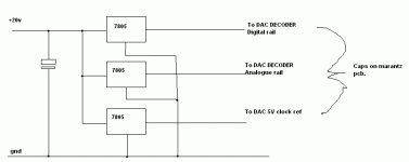
all three inputs for the 7805 can be connected to each other? same for grounds? only the output must be separated from each other.
correct?
gy21 said:
One more question
all three inputs for the 7805 can be connected to each other? same for grounds? only the output must be separated from each other.
correct?
Yes
Ideally seperate psu for each is much better but lets start simple.
Here is a simple diagram
Attachments
rowemeister said:
Yes
Ideally seperate psu for each is much better but lets start simple.
Here is a simple diagram
Brent
thats not very well isolated between digital analogue or grd's
allan
awpagan said:
Brent
thats not very well isolated between digital analogue or grd's
allan
It is a very basic way of doing it like I said.
It does give improvements to the sound BTW.
I could spend 20 mins writing how I did mine and just confuse people who are not electronically minded.
Brent
rowemeister said:
It is a very basic way of doing it like I said.
It does give improvements to the sound BTW.
I could spend 20 mins writing how I did mine and just confuse people who are not electronically minded.
Brent
basic reg,
in>cap>reg>cap>out
by three
analogue earth, digital earth
separate for later
what i have been saying, separate earths
improves reg's capability to regulate
allan
awpagan said:
basic reg,
in>cap>reg>cap>out
by three
analogue earth, digital earth
separate for later
what i have been saying, separate earths
improves reg's capability to regulate
allan
Hi,
That sounds good, but not especially practicable. My star earth board is already getting a bit impossible to manage with so many thick wires soldered to it

Simon
Just a noobie thought inspired by the earthing on the CD63, but would there be any merit in creating a local star earth point for the regs on the reg board?
So you'd have each one wired to one spot but not sharing a strip on the veroboard. Then the star would go to the main star.
So you'd have each one wired to one spot but not sharing a strip on the veroboard. Then the star would go to the main star.
Re: Re: DAC output filter and supplies
Hi Ray,
I'm impressed that you can remember where all this stuff is !!!!!
I cannot remember what happened yesterday !
Andy
6h5c said:
Hi Ray,
I'm impressed that you can remember where all this stuff is !!!!!
I cannot remember what happened yesterday !
Andy
Re: Re: Re: DAC output filter and supplies
LOL
Poor old Andy
Brent
poynton said:
I cannot remember what happened yesterday !
Andy
LOL
Poor old Andy
Brent
Re: Re: Re: Re: DAC output filter and supplies
who you calling old ?
Poor yes !
rowemeister said:
LOL
Poor old Andy
Brent
who you calling old ?
Poor yes !
Gooch said:
avr300
Are those Trent clock pcb's your using for the reg's?
Nice work looks cool.
Dave
Nope. Fleas from PFM, see http://www.acoustica.org.uk/
And correct, they basically are HQ regulators set for 5V, and Tent labs XO just seems to fit. 🙂
Voltage can be changed if used without the XO.
6h5c said:
Hey, nice one avr! Looks good with christmas too!
Ray.
Christmas tree - get out of here. How would you mount these? Next version should be a blade edition connecting to a backplane.😀
- Home
- Source & Line
- Digital Source
- Marantz CD63 & CD67 mods list


