poynton said:
Very nicely put together - how about adding some small photos to the pdf? [as you have for the clock divider] It may benefit newcomers to the thread.
Andy
I have thought of that 😀 + it will gloss up the list a little.
Brent
poynton said:
Very nicely put together - how about adding some small photos to the pdf? [as you have for the clock divider] It may benefit newcomers to the thread.
Andy
very nice brent😀
what next???
bypass pcb, just keep it for display and control
custom pcb for decoder dac and output

allan
awpagan said:
very nice brent😀
what next???
bypass pcb, just keep it for display and control
custom pcb for decoder dac and output
allan
I will at some point do a custom pcb for output and get rid of op amps.
Also I have thought of a better DAC (if there is one)
Brent
awpagan said:
very nice brent😀
what next???
bypass pcb, just keep it for display and control
custom pcb for decoder dac and output
allan
Well, the front panel has not been looked at yet [apart from screening the ribbon] so there is room for more playing !
Changing the DAC is not a technical problem - the decoder outputs i2s so it could be a TDA1541A S2 or one of the latest chips in 8x oversampling
OR
How about a discrete R2R ladder DAC ?
Andy
rowemeister said:
I will at some point do a custom pcb for output and get rid of op amps.
Also I have thought of a better DAC (if there is one)
Brent
passive discrete buffer😀 😀 😀 😀 😀 😀
taken from 10k resistor position, separate pcb for filter, buffer then to output
better dac's 🙄 probably each has there own views.
main part i think is implementation.
allan
poynton said:
Well, the front panel has not been looked at yet [apart from screening the ribbon] so there is room for more playing !
Changing the DAC is not a technical problem - the decoder outputs i2s so it could be a TDA1541A S2 or one of the latest chips in 8x oversampling
OR
How about a discrete R2R ladder DAC ?
Andy
I saw the i2s out and been looking at different dac's
prefer voltage out rather than current
also 256,384fs so can run with the cd850 and cd67
the TDA1541A S2 is very hard to find and very expensive unless you scrape a machine for parts, but it seems a waste of a player.
allan
Re: humble me
Hallo Rein,
If you need some assistance (in dutch), just drop me an e-mail.
Unfortunately for you I am in Noord-Holland, but you are welcome 😀
I have taken a lot of pictures during my mods that could be of help.
Groeten,
Raymond.
Rein said:I started to read this tpic, but already very soon it got to difficult for me. Perhaps time to start a topic for those like me who have not the knowledge others have.
Just another question, isn't there a Dutch "modder" in Limburg. Just to have th epossibility to see one time what has been done. By the way, I did not went shopping yet. The bitum, do you have to glue it on the inside of the top en the sides?
Rein.
Hallo Rein,
If you need some assistance (in dutch), just drop me an e-mail.
Unfortunately for you I am in Noord-Holland, but you are welcome 😀
I have taken a lot of pictures during my mods that could be of help.
Groeten,
Raymond.
Attachments
I'm thinking of putting in a separate reg (7805) for the dac. Does anyone have a more detailed description of how to do this?
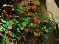
avr300 said:Like this?
😉
look out the fleas are breeding
beware of infestations
see your local vet for solutions
allan

Like this?
avr300
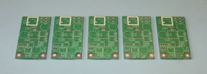
Are those Trent clock pcb's your using for the reg's?
Nice work looks cool.
Dave
avr300 said:Like this?
😉
I was more thinking of inserting one 7805 to feed the dac
6h5c said:Look what the mailman just brought in....😎
Now I have to get me some parts. Anyone have some 797's to spare? 😀
13 euro's at Farnell 😱.
Ray.
I just ordered two AD797 samples 😉
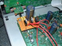
gy21 said:
I was more thinking of inserting one 7805 to feed the dac
Really you need 3 7805 mate. One for the digital supply one for the analogue supply and one for the voltage reference for the clock. Also supply the decoder from these too.
Here is a very basic way of doing it.
Attachments
gy21 said:I'm thinking of putting in a separate reg (7805) for the dac. Does anyone have a more detailed description of how to do this?
Hi,
You need a few things, and need to decide how far to take it. Do you want a separate reg for each of digital, analogue and clock reference? I think you do...
Basically, you need:
3x 7805
a strip of veroboard/stripboard about 5 strips wide and about 5" long
wire not too thick to be inserted through pcb holes (stranded would be the easier)
2 caps for each reg (one before, one after)
possibly some screwdown terminals to allow removal of the power input for repair/work (your choice, but I like that idea)
You need to know:
*Where to take the voltage from (I used the +20v supply from)under C803.
*What parts to remove (RD01 and RD04)
*Where to feed the new 5v rails (U200 - lifted at the supply end will feed the DAC's analogue psu pins, hole of RD04 for digital psu pins, and hole of RD01 for clock ref. pin)
This post of mine has a pic showing more or less where they go and what it might all look like: http://www.diyaudio.com/forums/showthread.php?postid=910675#post910675
Also - you need to attach the ground of the regulator and associated caps to the ground of the player, in my case a star ground I added.
edit: or do it even more simply as Brent has shown above (fewer caps).
SimontY said:
Hi,
You need a few things, and need to decide how far to take it. Do you want a separate reg for each of digital, analogue and clock reference? I think you do...
Basically, you need:
3x 7805
a strip of veroboard/stripboard about 5 strips wide and about 5" long
wire not too thick to be inserted through pcb holes (stranded would be the easier)
2 caps for each reg (one before, one after)
possibly some screwdown terminals to allow removal of some the power input (your choice, but I like that idea)
You need to know:
*Where to take the voltage from (I used the +20v supply from)under C803.
*What parts to remove (RD04 and RD04)
*Where to feed the new 5v rails (U200 - lifted at the supply end will feed the DAC's analogue psu pins, hole of RD04 for digital psu pins, and hole of RD01 for clock ref. pin)
This post of mine has a pic showing more or less where they go and what it might all look like: http://www.diyaudio.com/forums/showthread.php?postid=910675#post910675
Thanks Simonty and Rowemeister.
One question. My tentlabs clock is already on a dedicated board with a power supply (tentlabs schema), so does that mean I don't need the 7805 for clock ref anymore?
gy21 said:
Thanks Simonty and Rowemeister.
One question. My tentlabs clock is already on a dedicated board with a power supply (tentlabs schema), so does that mean I don't need the 7805 for clock ref anymore?
No, I believe it doesn't mean that. This is a pin on the DAC and your masterclock needs an additional psu. So you'll still need 3 to run the DAC sweetly.
Simon
- Home
- Source & Line
- Digital Source
- Marantz CD63 & CD67 mods list