Yes. I have one of Guido Tent's clocks - it just needs to be popped onto a PCB with a regulator.
I thought tomorrow might be nice. Doubtless, I will find that designing and making the PCB will take longer than expected. But now that I have CD5400 spread all over the bench, it needs something doing with it rather than just tamely putting it all back together again without doing anything. Assuming that the mod is successful, I'll post full details.
You've got a nice vibe  going! Somtimes you'll just need to break things to get yourself to actually do something 😉
Besides the clock, I guess the DAC upgrade will also make one of the bigger differences, I'm still not exactly sure how to do that though.
going! Somtimes you'll just need to break things to get yourself to actually do something 😉Besides the clock, I guess the DAC upgrade will also make one of the bigger differences, I'm still not exactly sure how to do that though.
The PCB has been made, stuffed, and tested. Time for a break, then start looking at cutting tracks etc on the CD5400.
I'm nearly there, and haven't had to cut any tracks, so it can all be put back if necessary. It's the deliberate errors in the manual that cause the trouble. For example, R619 doesn't exist and has been replaced by J114.
true, and R618 is just cut out, that would mean no MCLK..
edit: actually, at the underside, a lot more had been chaned. They added two 100uF caps, one of them with a series reistor between earth and and R610.
and the IC output of R618 is connected to R609, so that is effectively the same as bypassing R618.
You could simple cut the lines near the DAC and the servo, and connect the new clock directly to it I guess..
It works.
I'll take a photograph of the innards and write up how to do it tomorrow. Right now, I'm off to have a beer and listen to some Bach.
I'll take a photograph of the innards and write up how to do it tomorrow. Right now, I'm off to have a beer and listen to some Bach.
Nice 😀
Tell us if the sound has improved and enjoy your drink!
Btw, what clock did you use? The Tent XO with custom power supply? Did you use the schematic from their website?
Tell us if the sound has improved and enjoy your drink!
Btw, what clock did you use? The Tent XO with custom power supply? Did you use the schematic from their website?
Well, it's so long since I've listened to this player and I'm having to listen on headphones because I don't have a volume control handy (just don't ask) that I can't really compare. But it sounds very detailed and I'm hearing stuff I haven't heard on my other CD player (CD63mkIIKI with ALW clock mods).
I used Guido Tent's clock module with his power supply (but slightly modified). I didn't have a 7808 fixed regulator, so I used a 317 plus a few bits and pieces instead. Similarly, I didn't have the transistor he used, so I used a BC549C. I doubt if there's any difference. If there's any difference between my (slightly modified) implementation of Guido's circuit and his X02 board, then it's more likely to be due to PCB layout.
I used Guido Tent's clock module with his power supply (but slightly modified). I didn't have a 7808 fixed regulator, so I used a 317 plus a few bits and pieces instead. Similarly, I didn't have the transistor he used, so I used a BC549C. I doubt if there's any difference. If there's any difference between my (slightly modified) implementation of Guido's circuit and his X02 board, then it's more likely to be due to PCB layout.
Sounds good.
So, what did you do now? Cut the clocks near the two chips and solderd the clock output directly to the pins? So you used the 16.xx Mhz clock? Where did you get the supply voltage from?
Oh well, I guess, I'll wait for the pix 😀
I also wanted to use the diy XO with a slightly modified version, using a 2.2 mH inductor in series and a 2200uF/0.1 uF in paralell with the 7808 as an extra filter. Not sure if it should go before or just behind the 7808 though. Any thoughs?
I guess, I'll order the stuff tomorrow if we have do new order at work, together with the opamps and some new caps and stuff...
I'm really excited!
Um. It was a bit frantic when I started listening, but it sounds seriously good now. I think I'm going to be up late tonight.
I removed J013 and J114. I connected the new 16.9344MHz clock directly to the DAC end of J013 and took another bit of wire from there to the invertor input end of J114. I removed the 8.4672MHz crystal. I picked up 0V on J014 and +12V on J178.
I removed J013 and J114. I connected the new 16.9344MHz clock directly to the DAC end of J013 and took another bit of wire from there to the invertor input end of J114. I removed the 8.4672MHz crystal. I picked up 0V on J014 and +12V on J178.
I connected the new 16.9344MHz clock directly to the DAC end of J103 and took another bit of wire from there to the invertor input end of J114.
Don't you mean J013 comming directly from the dac clock input? At least that's what it's called in the service manual 😉
OK, it's time I went to bed. It's sounding seriously good and I've even tried using the "pitch" control; the numbers on the display change but not a sound is heard (phew).
Can you imagine 6dB/octave 1/f noise with a slowly falling corner frequency? That's what the biggest change over the hours that I've listened sounded like. When I first fired it up, the corner frequency sounded as though it was somewhere near 1kHz (give or take an octave), but it's fallen so that the entire audio band is now clean. In addition, I'd say that the white noise floor has also fallen, perhaps by 3dB. All in all, well worth the effort.
Can you imagine 6dB/octave 1/f noise with a slowly falling corner frequency? That's what the biggest change over the hours that I've listened sounded like. When I first fired it up, the corner frequency sounded as though it was somewhere near 1kHz (give or take an octave), but it's fallen so that the entire audio band is now clean. In addition, I'd say that the white noise floor has also fallen, perhaps by 3dB. All in all, well worth the effort.
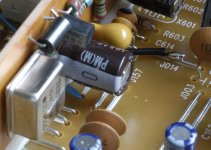
As promised, I've taken pictures. The first picture shows a general view of my board and how the 0V is picked up from J014.
If you look carefully towards the bottom left, between the Tent clock and the electrolytic capacitor, you can see a pair of blue wirewrap wires going into the DAC end of J013. One takes the new clock into the DAC, and the other goes on to the input of the invertor feeding the microcontroller.
If you look carefully towards the bottom left, between the Tent clock and the electrolytic capacitor, you can see a pair of blue wirewrap wires going into the DAC end of J013. One takes the new clock into the DAC, and the other goes on to the input of the invertor feeding the microcontroller.
Attachments
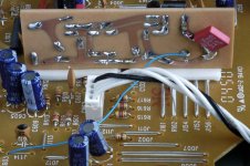
This picture shows the back of the board. At 16.9344MHz a few millimetres of PCB track is an inductor so the 100nF power supply decoupling capacitor is soldered directly between the 0V and +5V pins of the Tent clock.
Although it looks like one wire, the blue wirewrap wire coming out of the clock goes under the board, to the DAC, then another returns to go to the invertor input end of J114.
As you can see, the board is held in place simply by a pair of sticky pads. It weighs nothing, after all.
Although it looks like one wire, the blue wirewrap wire coming out of the clock goes under the board, to the DAC, then another returns to go to the invertor input end of J114.
As you can see, the board is held in place simply by a pair of sticky pads. It weighs nothing, after all.
Attachments
- Status
- Not open for further replies.
- Home
- Source & Line
- Digital Source
- Marantz CD5400 clock replacement